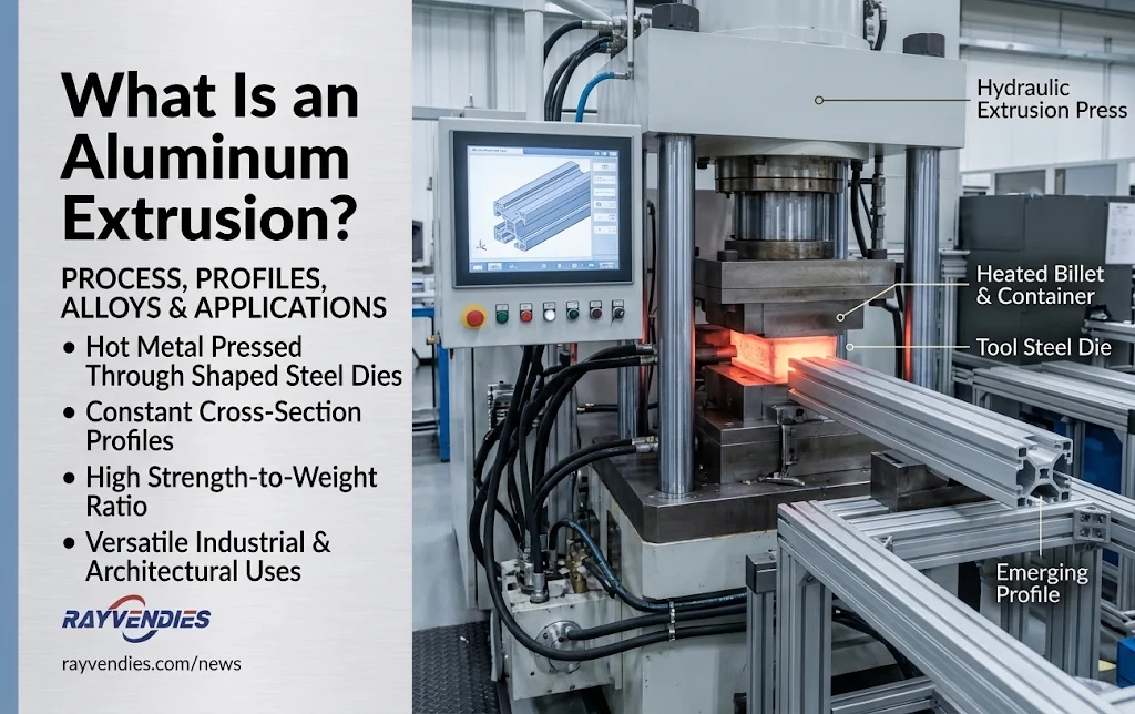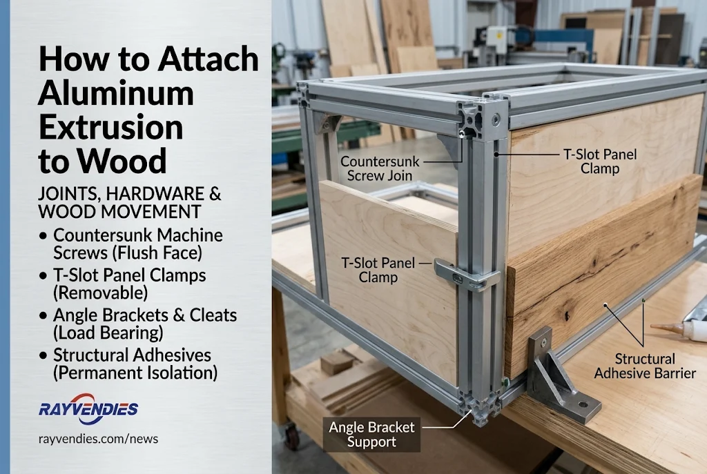
Aluminum framing is the default structure for machine guards, workstations, and automation cells because it can be assembled, modified, and rebuilt with hand tools. That flexibility depends on small components that never appear on a frame drawing: the nuts, brackets, caps, hinges, and feet that turn cut profiles into a structure. Ordered late, brackets will not seat and caps will not fit the groove.
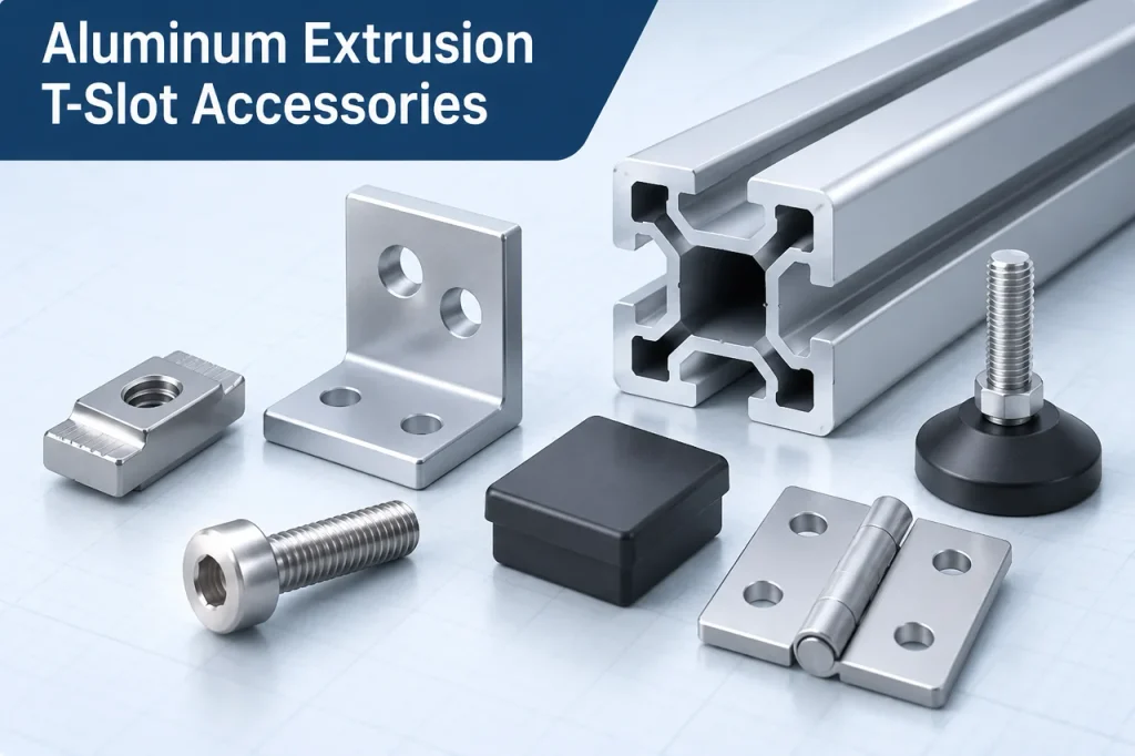
Aluminum extrusion T-slot accessories are the standardized components that engage the open channel running along an extruded aluminum T-slot profile: T-nuts and bolts create adjustable threaded connections, brackets and plates transfer load between members, end caps and slot covers close the groove, and hinges, handles, feet, and casters add function. The hardware fits when its nut or rail matches the slot opening, the cavity depth below it, and the hole pattern of the bracket it serves, so compatibility is confirmed against a dimensioned drawing rather than a series name.
The sections below follow the order in which those decisions are usually made at the drawing board.
What Are T-Slot Accessories and Why Must They Match the Profile?
A T-slot profile carries a channel shaped like an inverted T: a narrow opening at the surface widens into a broader cavity below. A nut enters, rotates ninety degrees, and is trapped by the lips; a bolt through a bracket then pulls nut, bracket, and profile into a clamped joint. The channel offers a continuous run of positions, so nothing needs welding.
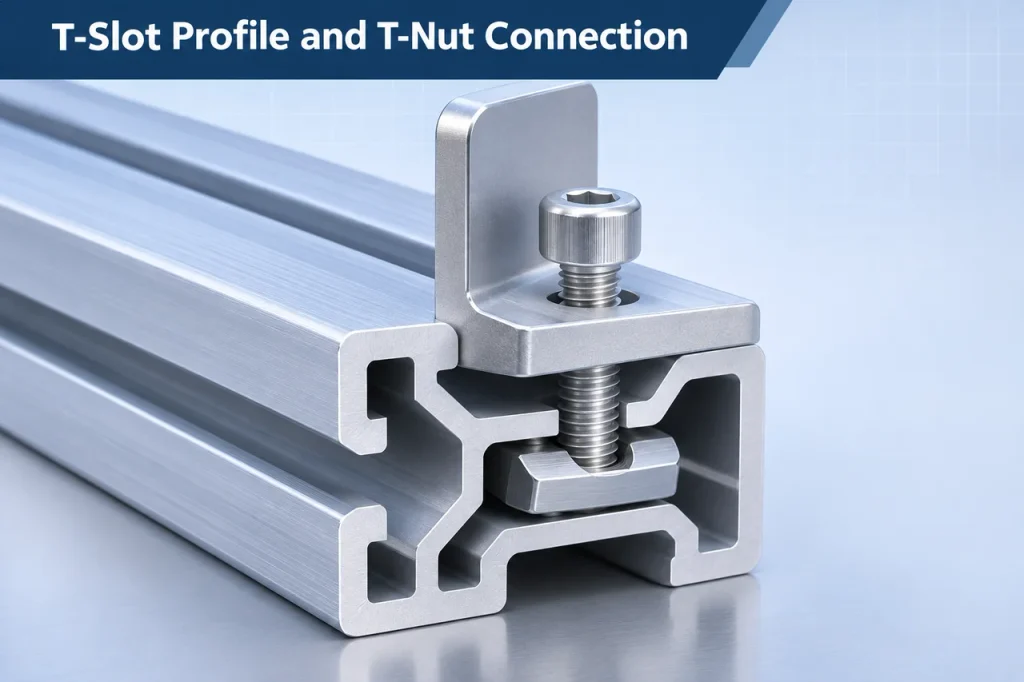
Slot geometry is fixed at extrusion, so the cross-section is the first accessory decision: the T-slot aluminum profiles in a family determine every part that can later be attached. That is why T-slot profile design starts with the hardware list rather than with the outline. Joint stiffness depends on hardware class as much as profile, as this guide to aluminum extrusion connections sets out for bolted, internal, and connecting-plate methods.
Five checks decide whether an accessory works: slot opening width at the lips, slot depth, lip and shoulder geometry, center bore and hole spacing, and thread standard, because an imperial nut and a metric bolt cross-thread both parts. Even within the EN 755-9 tolerance band a slot opening can vary by several tenths of a millimeter between batches, and extrusion tolerances set how much of that variation reaches the slot, so a joint can feel loose at one end of a long member and jammed at the other. Test-fit a sample nut before a bulk order.
Fasteners: T-Nuts, Bolts and Thread Selection
Fasteners should be the first accessory decision, not the last. Every bracket, hinge, foot, and retainer depends on a nut seated in a slot, and the nut’s thread size sets the bolt, the bracket hole, and the load path into the profile. Common catalogs group M3 to M5 hardware with 6 mm slots, M5 to M8 with 8 mm slots, and M8 to M10 with 10 mm slots, but that grouping is a starting point, not a rule the slot width alone enforces.
| Type | How It Installs | Best For | Limitation |
| Slide-in (standard) | Threaded on and inserted from the profile end | Maximum clamp load and contact area | Needs partial disassembly on a closed frame |
| Roll-in | Rotated into the slot at any point | Retrofits and late additions | Less contact area than slide-in |
| Drop-in | Fits through the slot opening directly | Fast additions in the field | Lower load rating in small sizes |
| Spring-loaded | Spring holds position on vertical faces | Vertical and overhead work | Slightly higher cost |
| Anti-rotation block | Block with a square thread bore | High-torque and moving joints | Bulky in tight corners |
An 8 mm slot can carry an M8 nut from one supplier and reject it from another, because what actually captures the nut is the combination of opening width, cavity height and width, and lip thickness, none of which is standardized across brands. Two further limits sit outside the slot: the nut’s bearing area against the lips governs how much clamp load it carries before the profile distorts, and it reaches this limit well before the bolt does. Treat any published slot-to-thread table as a shortlist to verify, then confirm the specific nut against the specific section.
Bolt Heads, Torque and Joint Failure
Socket head cap screws are the default, since the compact head bears against bracket faces in tight corners. Button head screws sit lower for panel mounting, countersunk screws sit flush, and hammer-head bolts combine nut and bolt in one piece for face-mounted accessories. Tighten to the torque published by the profile system and fastener manufacturer for that exact nut and bolt combination. Where no figure is published, do not substitute a blanket value or add extra turns: torque depends on thread size, bolt property class, lubrication, nut geometry, and the wall thickness it clamps against, and an extra quarter turn on a die-cast bracket or a thin-walled section can crush the lip or strip the nut. Establish the setting by testing a joint on an offcut instead.
Two failure patterns explain most problems: a bolt that is too long bottoms out on the far wall of the channel, feeling tight while applying almost no clamp load, and a bolt that is too short engages few threads and strips the nut. Verify the finished joint rather than trusting the wrench: check that the nut has not rotated in the slot, that the bracket face sits flat with no gap at the corners, and that the member has not been pulled out of line by the clamping force. A second fastener across the bracket resists rotation about the bolt axis, but it is one factor among several.
Structural Connectors: Brackets, Plates and Hidden Joints
Connectors, not profiles, decide how stiff a frame feels. A large profile with undersized brackets will deflect and rack, while a modest profile with gusseted connectors and bracing can behave far more rigidly than its section suggests.
Two failures matter. Racking deforms a rectangular frame into a parallelogram under sideways force. Creep is subtler: a bracket on a single nut rotates about it under sustained load, drifting the frame over months. A second fastener per bracket addresses the rotation that drives creep and stiffens the corner, but racking is resisted by the whole load path. Section size, span, load position, and bracing all enter, and a frame can still rack with two fasteners in every bracket if it has no diagonal restraint.
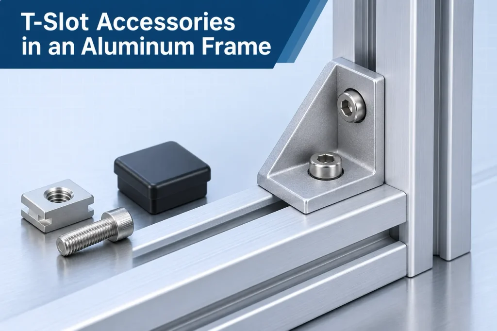
90-Degree Corner Solutions
| Connector | Appearance | Stiffness | Typical Use |
| Standard angle bracket | Visible on two faces | Moderate | Light frames, panels, general assembly |
| Gusseted or reinforced bracket | Visible, with a raised web | High | Machine bases, guards, loaded corners |
| Die-cast corner bracket | Visible, rounded form | Moderate to high | Clean enclosures and workstations |
| Internal corner connector | Fully hidden | High when correctly installed | Furniture, display frames, visible structures |
The internal connector pulls two profiles together from inside the joint, but needs access holes placed correctly and cannot be adjusted without disassembly.
In-Line, Multi-Way and Bracing
Frames also need members extended, branched, or crossed. Splice plates span two profiles lengthwise to extend a run; L- and T-connection plates join members at right angles while leaving side slots open; cross plates join four profiles at one intersection; and multi-way connectors seat inside the profile end for an almost invisible joint. Brackets alone rarely solve racking in a tall frame: diagonal bracing across the open face converts a rectangle into two triangles, and a second bracket at a loaded joint adds moment capacity through a longer lever arm.
Choosing Accessories by Profile Series
Profile series is the index to the accessory catalog. In metric systems the number is the outside dimension in millimeters, and slot width generally rises with it, setting the hardware class and load range.
| Series | Outside Size | Slot Width | Fastener | Typical Role |
| 15 | 15 x 15 mm | 5 mm | M3, M4 | Light enclosures, electronics |
| 20 | 20 x 20 mm | 5 to 6 mm | M4, M5 | Desktop frames, prototypes |
| 30 | 30 x 30 mm | 8 mm | M5, M6 | Workstations, displays |
| 40 | 40 x 40 mm | 8 mm | M6, M8 | Machine frames, guards, conveyors |
| 45 | 45 x 45 mm | 10 mm | M8, M10 | Heavy machinery, automation cells |
| 80 | 80 x 80 mm | 10 mm | M8, M10 | Large bases, gantries |
These figures describe common metric framing systems and are not a standard every manufacturer follows. Treat the table as a reference to check against a catalog drawing rather than as a compatibility guarantee, and remember that a metric 40 and an imperial 1.5 inch section often look alike and share no hardware.
Slot width does not scale with outside size, and a metric 20 mm section and an imperial 2 inch section can share a designation while sharing no hardware, so specify slot width plus thread standard rather than a series name. Anyone working in the small end of the range should check 2020 aluminum extrusion dimensions before ordering nuts, because the slot there is often the tightest in the family. The 40 series is the most widely supported size in metric framing: an 8 mm slot usually accepts M6 and M8 hardware, which covers guards, conveyor supports, and robot fencing, and most bracket, retainer, hinge, and caster families are built around it, so a design can move from a 30 series prototype to a 40 series frame for production aluminum extrusion applications without rebuilding the list.
Panel, Door and Enclosure Hardware
Enclosures are where accessory selection becomes most visible. Panels must be held without drilling, doors must swing without sagging, and open slots must be closed so chips and dust stay out.
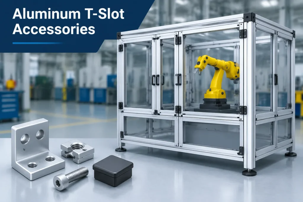
Panels, Doors and Finishing
Panel retention uses the slot as the clamping feature. A panel retainer strip snaps into the slot and captures the sheet edge, holding polycarbonate, acrylic, composite, or mesh without a hole; a clamp-and-screw retainer grips the panel with a block fastened into a T-nut. A retainer sized for 3 mm polycarbonate will not grip 5 mm material and cracks the corners if forced. On a protective enclosure a friction-only retainer can release under impact, so add a mechanical clamp.
Door hardware fails in a predictable order: the hinge loosens, the door sags, the latch stops engaging. Small doors need one pair of surface hinges, taller doors well-spaced or continuous hinges, and any door above roughly a meter a stay or gas strut. Handles should be through-bolted to the panel.
End Caps, Slot Covers and Finish
End caps and slot covers are the finishing layer, and they do more than look tidy:
- End caps close the cut cross-section, removing the sharp edge, keeping chips out of the internal channel, and finishing the frame.
- Slot covers fill unused groove length, producing a surface that wipes down and will not collect swarf.
- Edge banding and inset strips conceal the panel-to-profile junction and close the dust gap.
On anodized frames, hardware and profiles from different batches often differ in tone, so specify the finish of the whole package with the profiles.
Base, Mobility and Cable Management
Every frame meets the floor, and most meet cables. Base hardware decides whether the structure sits level and stays put; cable management decides whether it stays serviceable. Both are routinely left off the first order and both are hard to add later.
Leveling feet lift the frame off the floor, compensate for an uneven slab, and isolate it from standing water. The thread must match a T-nut in the slot or a tapped insert in the foot plate, and the base must spread the point load without denting a soft floor. Foot plates widen the footprint where the structure is tall or carries a moving load; a frame neither anchored nor braced is a tipping risk.
Casters turn a fixed bench into a mobile unit. Hard nylon rolls easily on concrete but transmits vibration and marks resin floors; soft rubber protects the floor but needs more push force; polyurethane sits between the two. Specify load rating per caster with a safety factor for uneven floors, fit locking casters on at least two wheels, and mount them to a plate spanning two slot positions so rolling load cannot loosen a single T-nut. Cable clips snap into the same groove, keeping harnesses off the floor. Steel fasteners touching aluminum invite galvanic corrosion under road salt, so barrier washers and anti-seize are standard on frames that travel.
Building a Bill of Materials and Assembly Sequence
An accurate accessory list is built from the frame drawing, not from a catalog. Count connection points, apply a per-point fastener allowance, add a service margin, then add the families whose quantity follows from the design.
Step 1: List Accessories by Function
Building an aluminum extrusion T-slot accessories list means working through six groups in order while the layout is still open: structural (brackets, plates, gussets, bracing), fastening (T-nuts, bolts, washers, thread-locker), panel and door (retainers, gaskets, hinges, handles, latches), finishing (end caps, slot covers, edge strips), base and mobility (feet, casters, floor anchors), and utility (cable clips, stops, bumpers). The grouping exposes omissions: a drawing shows members and brackets, not end caps, yet every cut end needs one.
Step 2: Count Nodes and Apply a Fastener Factor
Each bracket-to-profile connection needs one nut and one bolt; each internal connector or panel clamp adds its own set. The margin is not padding: loose nuts fall into bases and vanish.
| Item | Counting Method | Margin |
| Corner brackets | Count corners and mid-span joints | Add 10 percent for field changes |
| T-nuts and bolts | One pair per bracket screw hole | Add 15 to 20 percent |
| End caps and retainers | Every cut end; linear meters per panel edge | Add 10 percent for waste |
| Hinges and latches | Per door leaf | One spare set per project |
Step 3: Confirm Compatibility, Then Assemble
Check every line against the profile series: slot width, thread size, hole pattern, and load rating, tagging each to its member where series are mixed. Then assemble in a fixed order:
- Deburr all cut ends. A burr stops a bracket seating flat and costs more rigidity than any bracket upgrade.
- Dry-fit the whole frame hand-snug. Nothing is torqued yet.
- Measure both diagonals of each rectangular face. Equal diagonals mean the face is square.
- Torque in a diagonal pattern, center outward, so the frame does not walk out of square as preload builds.
- Re-check diagonals after the first week of service, especially on mobile equipment.
The common errors repeat: mixing series within one frame, too few fasteners in high-load corners, over-tightening die-cast brackets, and closing every slot so no connection point remains. Spare slot access is the capability that justified extruded framing.
How Custom Profiles Change the Accessory Plan
Custom profiles may not be compatible with standard T-slot accessories unless their slot geometry is deliberately designed to match an established profile system. Slot opening, cavity depth, lip thickness, wall thickness, and internal ribs are all set by the die, so an accessory plan either adopts a known system or is tooled alongside the section. Either way, it belongs in the die design conversation, not in procurement after delivery.
Three consequences follow. Slot geometry must be designed for hardware: a slot that looks generous but is shallow in the capture region will not hold a nut under torque, so model it around the required parts. Where a custom section reproduces the slot of an established series closely enough, standard nuts and caps often still fit, which saves tooling on every downstream part. End caps and slot covers may become custom parts: if the cap is a press-fit, the slot opening tolerance becomes a functional dimension. Connection points may need machining: where a custom section meets a standard actuator bracket, an adapter plate is more dependable than modifying the section. The section and the hardware list have to be reviewed as one document, which is what separates a profile that looks right on paper from one that assembles.
Matching the Accessory Plan to a Custom Section
Most accessory problems are settled before a single profile is cut, at the point where the section is either chosen from an existing system or drawn from scratch. Choosing an established series means the nut, bracket, cap, hinge, and caster catalogs all apply unchanged. Drawing a new section means deciding deliberately whether to reproduce an existing slot geometry and inherit that catalog, or to design a new one and accept the tooling that comes with every mating part, which is where custom extrusion die services earn their cost.
A new section is usually the right answer when the design needs something the standard range cannot give: an integrated cable channel, a wider mounting face, a hollow for a specific insert, or a wall thickness driven by a load case rather than a catalog. In each of those cases the failure mode is the same, and it is geometric rather than metallurgical: a slot that measures correctly but sits where no bracket can reach, or a cavity that is deep enough for a nut but too narrow for the bolt head above it.
Need a custom T-slot aluminum profile? If you are specifying a section rather than buying one from stock, send the cross-section drawing, the intended slot opening and cavity dimensions, the accessories you plan to use with it, and your annual or first-order quantity. Contact our extrusion die team with those four items and the review can confirm, before tooling starts, whether standard hardware will fit the section or whether a mating part needs to be designed alongside it.
FAQ
Can accessories from different profile series be mixed within one frame?
Only where the hardware is tagged to the correct member. A 40 series bracket cannot mount to a 20 series profile because hole pattern and slot width differ, but 40 series for the base and 20 series for a light enclosure is workable. Order by member rather than by project, or the box arrives mixed with no way to tell which nut belongs where.
What should be done when a T-nut spins loose inside the slot?
A spinning nut usually indicates low preload, poor slot engagement, or a nut undersized for the slot depth. Check that the bolt gives full thread engagement without bottoming out. If the nut rotates freely, fit a larger-contact slide-in nut or an anti-rotation block, and check the bracket hole for elongation. Loosening on vibrating equipment calls for thread-locker.
Do accessories need to come from the same supplier as the profiles?
Not necessarily, but verify compatibility before ordering rather than assuming it. Take exact slot width and depth from the drawing and test-fit sample nuts and brackets on an offcut, especially brackets and end caps, whose fit depends on the corner radius.
What torque should be used when the supplier publishes no value?
None should be assumed. Ask the profile system or fastener supplier for the figure that applies to the specific nut, bolt, and section, and if it is not available, determine a setting by testing a joint on an offcut of the same profile. Thread size, bolt property class, lubrication, nut geometry, and wall thickness all change the answer, and a rule of thumb carried over from another system can crush a lip or strip a nut.
Can standard accessories be used on a custom extrusion?
Sometimes, and it depends entirely on the slot. If the custom section reproduces the slot opening, cavity depth, lip thickness, and bore spacing of an established series closely enough, the hardware for that series usually works. If any of those dimensions differ, the nut may not seat, the cap may not clip in, or the bracket may sit off the member. Confirm on a sample before committing to a tooling order, because the slot geometry is far harder to change after the die is cut than the accessory list is.
Meta Description: Aluminum extrusion T-slot accessories explained: T-nut types, slot width checks, torque practice, bracket selection, BOM counting and assembly order. Focus Keyword: aluminum extrusion t-slot accessories Slug: aluminum-extrusion-t-slot-accessories