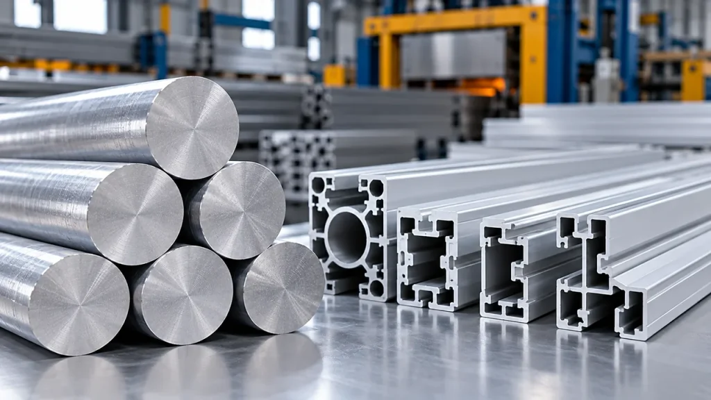
A profile can look clean on a CAD screen and still fight the press. Hot aluminum squeezes through a steel die under tons of pressure, and it takes the easiest path it can find. When the cross-section sends that flow unevenly, the result is twist, surface tears, slow production, and die repairs nobody budgeted for. Most of these problems trace back to choices made long before tooling is cut.
Aluminum extrusion design is the work of shaping a profile’s cross-section so it extrudes fast, straight, and at low scrap. The rules that matter most: keep wall thickness variation under 2:1, round every corner, keep the section symmetrical, watch the circumscribing circle diameter, default to standard tolerances, and review the drawing with a die maker early. A custom aluminum extrusion dies manufacturer can spot the features that will stall a press, and a short design review at this stage costs far less than a die correction later.
This aluminum extrusion design guide walks through the process logic behind those rules, then the core guidelines, sizing and tolerance limits, design tools, cost drivers, and the workflow for a custom profile.
What is aluminum extrusion design?
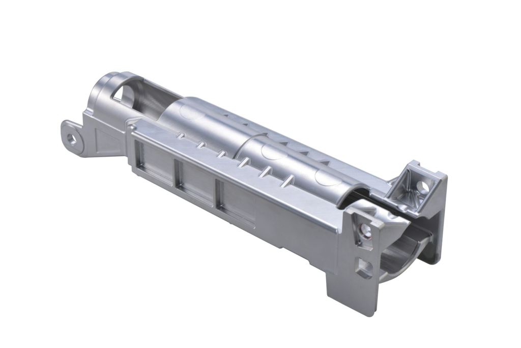
Aluminum extrusion design is the process of engineering a profile’s cross-section—its walls, corners, ribs, and cavities—so the aluminum extrusion process can produce it at production speed with stable dimensions and low scrap.
An extruded profile starts as a two-dimensional cross-section drawn out to length. That shape freedom is the process’s biggest advantage: you put metal only where the part needs it, and you can combine functions—flanges, screw ports, heat fins, cable channels—into one piece with no welding or assembly. The trade is that the die has to push metal through every part of that shape at the same rate.
Here’s where the process constrains the design. A heated billet is pressed through the die, the profile exits into an air or water quench, and then a stretcher pulls it straight before cutting. Metal follows the path of least resistance, so thick zones race while thin zones starve. Nearly every rule in this guide exists to keep that flow even.
The three profile families
Aluminum extrusion profiles fall into three groups, and the group that decides dies costs more than anything else:
- Solid profiles have no enclosed void. The die is a flat plate with the shape cut into it, which makes these the cheapest to tool and the fastest to run.
- Semi-hollow profiles nearly close a void, like a C-channel with a narrow gap. The die tongue that forms the gap carries heavy stress and wears faster.
- Hollow profiles fully enclose a void. They need a porthole or bridge die with a mandrel, and multi-cavity hollows are the most demanding tooling in the shop.
The complexity order stays fixed: solid, then semi-hollow, then hollow. Custom hollow aluminum extrusion dies need ports, bridges, and welding chambers sized around the cavity, so it’s worth asking whether the function truly requires a closed void before committing to one.
What is aluminum extrusion used for?
The same design rules carry across very different markets:
- Construction: window and door frames, curtain walls, structural framing
- Automotive and transportation: crash structures, battery trays, roof rails
- Electronics: heat sinks and housings where fins pull heat away
- Renewable energy: solar panel frames and mounting rails
- Furniture and interiors: chair frames, wardrobe rails, LED housings
- Industrial equipment: machine frames, workstations, conveyor rails
Each market adds its own twist—cosmetic finish in architecture, crash strength in transport, and fin density in electronics—but the cross-section rules below apply to all of them.
Core aluminum extrusion design guidelines
Four habits prevent most extrusion defects: keep walls uniform, round the corners, balance the section, and let ribs rather than bulk carry stiffness.
Wall thickness and transitions
Keep the ratio between the thickest and thinnest wall below 2:1 across the whole section. If the thinnest wall is 1.5 mm, don’t put a 5 mm boss beside it. Thick zones extrude faster than thin ones, and the mismatch builds internal stress that shows up as twist, bow, or waviness after cooling.
For 6xxx alloys, treat 1.2–1.6 mm as the practical minimum wall on mid-size profiles, though the exact floor depends on the alloy, the circumscribing circle, and the span between ribs. Thinner walls do exist, but they slow the press and wear dies faster, and the metal savings rarely cover the difference.
When thickness must change, blend it. Use a taper or a radiused step instead of a sharp shoulder, and give the transition a length of at least three times the thickness difference. It’s a common shop rule, and it prevents most flow-related surface marks.
Corners, radii, ribs, and fins
Sharp inside corners don’t survive extrusion. They stress the die steel, tear the profile surface, and cause trouble later—anodizing burns on sharp edges and powder coat pulls away from them. The Aluminum Extruders Council lists a minimum outside corner radius of 0.020 in and 0.015 in on inside corners. In metric terms, plan on 0.5–1.0 mm inside radii wherever space allows.
Ribs are the cheapest stiffness you can buy. A wide, thin section waves and twists, but a few well-placed ribs make it self-supporting, easier to straighten, and flatter off the press. Ribs carry functions too: grooves guide screws and drill bits, index marks tell similar-looking pieces apart, and webs separate cable channels. Keep rib thickness close to the parent wall so flow stays balanced, and for fin-type features like heat sinks, hold the height-to-gap ratio at or below 4:1 to avoid broken die tongues and wavy fins.
Symmetry and flow balance
Symmetrical sections extrude faster and straighter because flow and cooling stay even on both sides. When function forces asymmetry—a heavy mounting flange on one side, say—the die maker can add balancing features: false ports, flow pockets, or a temporary keeper web that holds a semi-hollow slit stable until it’s sawn off after extrusion. Expect slower speeds on unbalanced sections, and settle the trade before tooling rather than after.
The table below pulls the key numbers together.
| Design factor | Practical starting point | Why it matters |
|---|---|---|
| Wall thickness ratio | ≤ 2:1 across the section | Biggest single driver of twists and defects |
| Minimum wall, 6xxx alloys | 1.2–1.6 mm, verify with supplier | Depends on CCD and rib spacing |
| Inside corner radius | 0.5–1.0 mm | Larger radii extend die life. |
| Outside corner radius | ≥ 0.5 mm | Better coating coverage, less handling damage |
| Fin height-to-gap ratio | ≤ 4:1 | Prevents die tongue breakage and wavy fins |
| Circumscribing circle diameter | ≤ 203 mm (8 in) | Widest press availability at lower cost |
Sizing limits: CCD, weight, and tolerances
The circumscribing circle diameter, the weight per meter, and the tolerance class decide which presses can run your profile and what it costs per meter.
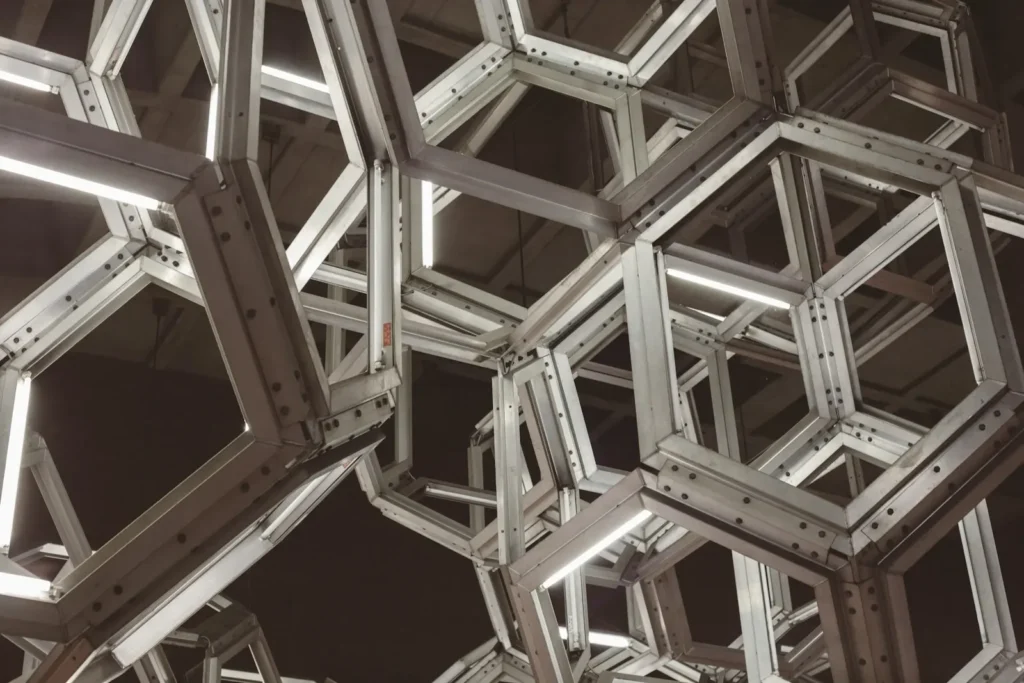
The circumscribing circle diameter (CCD) is the smallest circle that fits around your cross-section. It drives press selection, die size, and run speed. Most general presses favor profiles at or under 203 mm (8 in); large presses can reach about 457 mm (18 in), but supplier options shrink and prices climb as the circle grows. Folding features inward, shortening long cantilevered flanges, or splitting one oversized profile into two interlocking parts all shrink the CCD.
Weight per meter matters just as directly. Extrusion pricing tracks metal use and press time, so nonfunctional bulk is pure cost. If you need stiffness, move material away from the neutral axis instead of thickening the walls—that buys bending stiffness at a fraction of the weight. Dimension the drawing to metal faces and functional datums, not to theoretical centerlines inside voids, because that’s where measurement and tolerance actually live.
On tolerances, start with the standard families: the Aluminum Association tables in North America, ASTM B221, or EN 755-9 in Europe. These describe what presses hold at normal speeds. Tighter tolerances are negotiable but cost speed, die corrections, and inspection, so reserve them for sealing surfaces, mating fits, and critical visible dimensions.
What is an aluminum extrusion design tool?
An aluminum extrusion design tool is any software or structured review that tests a cross-section for manufacturability before the die steel is cut.
Three kinds are common. CAD-based checks flag wall ratios, corner radii, and aspect ratios against published guidelines while you draw. Metal-flow simulation models how aluminum fills the ports and bearings of a die, which helps with tricky hollows and thin fins long before any steel is machined. The third and most accessible option is the supplier DFM review, where a die maker reads the cross-section against the guidelines in this article and marks the risky features.
For a first pass, even a simple checklist of the rules above—wall ratio, radii, symmetry, CCD, tolerance class—catches most problems. Simulation earns its keep later, on profiles where a failed trial would be expensive.
How design choices drive aluminum extrusion price
The complexity, run speed, yield, and weight per meter set most of the piece price, and all four are locked in at the design stage.
| Cost lever | What raises it? | What lowers it? |
|---|---|---|
| The complexity | Multi-cavity hollows, precision tolerance classes | Fewer voids; solid or semi-hollow shapes |
| Run speed | Sharp transitions, deep narrow fins | Smooth blends, balanced sections |
| Yield and scrap | Uneven walls that tear or twist | Uniform walls, symmetric flow |
| Straightening and handling | Wide, thin, unsupported spans | Ribs that make the profile self-supporting |
| Weight per meter | Nonfunctional bulk | Lightening pockets, stiffness by geometry |
| Finishing effort | Sharp edges, cosmetic surfaces everywhere | Rounded edges, finish classes by visibility |
No single price list applies across shops, because billet cost, alloy, press size, and order volume all move the number. The direction is constant, though: balanced walls, generous radii, and a controlled CCD pull the price down, while tight tolerances and heavy multi-cavity hollows push it up. A design review that prevents even one die trial usually pays for itself in lead time alone.
Custom aluminum extrusion design: working with your die supplier
Send the die maker your cross-section, alloy, tolerance class, and finish before tooling, and treat their redlines as free engineering rather than pushback.
A useful quote package includes the 2D drawing and 3D model, alloy and temper, cut lengths, tolerance requirements, finish specification, and estimated annual volume. With that in hand, a die supplier can flag the features that will slow the press or shorten die life and often propose a small geometric change that keeps the function while simplifying the tool.
Two patterns come up again and again. A multi-void hollow, such as a tube with three internal channels for cable routing, can usually become a single larger cavity with two thin webs: the mandrel gets simpler, output rises, and the webs still guide the cables. A semi-hollow slit that must hold a tight width can gain a temporary keeper web during extrusion, then get sawn open before assembly, which keeps the gap dimension stable through quench.
Freeze the design before the trial. Sort dimensions into must-haves and nice-to-haves so that if the first trial runs slightly off on a noncritical face, the die can be approved without another correction cycle.
Frequently asked questions
6061 or 6063: which alloy should I choose?
6063 extrudes best and takes the best surface finish, which makes it the default for architectural profiles, decorative parts, and thin walls. 6061 carries higher strength and machines and welds well, so it suits structural and industrial parts, at the cost of slower extrusion and more die wear. Pick by the property the part actually needs, and confirm extrudability with the supplier before freezing the drawing.
Can an aluminum extrusion include internal threads?
No. Threads can’t be pushed through a die. The standard approach is to extrude a solid boss or an open screw port, then drill and tap it afterward, or design a T-slot that accepts a drop-in nut. Give the boss enough wall and blend it into the section so the tapped feature has material behind it.
What information does a die maker need to quote a custom profile?
Send the cross-section drawing or CAD file, alloy and temper, circumscribing circle size, wall thicknesses, tolerance class, required finish, cut lengths, and annual volume. Add the application if you can. A die maker who knows whether the part carries a load, seals a housing, or just covers something will make better calls on where to save cost.