A frame that wobbles after the last bolt is tightened is rarely reworked, only rebuilt, and the fittings are usually the reason.
T-Slot aluminum extrusion connectors are the fittings that lock two or more profiles together through or around the T-shaped slot: external types such as corner brackets, joining plates, and gussets that bolt on without machining, and internal types such as anchor, butt, and end fasteners that sit inside the cavity for concealed, high-rigidity joints. The right choice depends on the load, whether the joint must stay adjustable, and how much machining the build can absorb.
What follows covers slot geometry, both connector families, the sequence that keeps a frame square, and hardware selection.
Why Connector Choice Decides Frame Performance
A T-slot frame is a bolted structure, so every load path passes through a connector. Profiles resist bending as beams, but the joints govern deflection, squareness, and stability. Two frames built from identical profiles behave differently once the fitting changes, because a fitting that only clamps with friction creeps under vibration while one that locates and preloads does not.
Mechanical clamping leaves every joint a slip surface. Holding it demands faces that locate rather than rely on bolt tension, a body stiff enough for shear and moment, and a pad large enough to hold clamp under vibration.
What Is an Aluminum T-Slot?
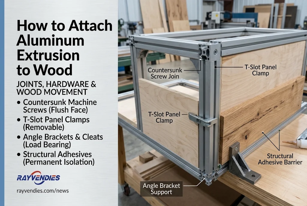
An aluminum T-slot is a profile extruded with one or more continuous T-shaped channels along its length. The narrow opening retains a nut while the wider internal flange carries the clamp load, so hardware can sit anywhere without drilling, and the same channel takes panels, hinges, and cable clips. Profiles are usually 6063-T5, which balances extrudability, corrosion resistance, and frame strength.
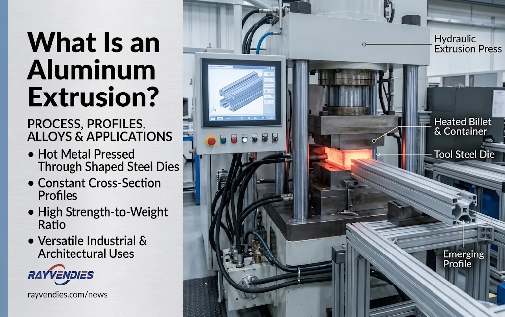
Because the channel is continuous, a nut slides in anywhere and the joint closes in minutes. Quality then depends on how well the connector engages it, and how aluminum extrusion works explains why slot size is locked once the die is cut.
Series are grouped by width, which implies a slot and fastener range, but these values are typical, not a standard; authoritative values come from the manufacturer’s drawing.
| Series | Typical Width | Typical Slot | Typical Fastener | Typical Use |
| 20 series | 20 mm | 6 mm | M4, M5 | Light enclosures, printer frames |
| 30 series | 30 mm | 8 mm | M6 | Benches, small guards, test rigs |
| 40 series | 40 mm | 8 mm | M6, M8 | Automation cells, robot bases |
| 45 series | 45 mm | 10 mm | M8 | Heavy guarding, gantries |
Width does not guarantee interchangeability. A 30 and a 40 series joint cannot be swapped, because slot width, flange depth, and bolt size change together: a bracket sized for the smaller slot cannot clamp the larger profile. Lip thickness varies between producers within one series too.
Slot Geometry That Determines Connector Fit
- Slot opening width. A one millimeter mismatch lets a nut rotate out under load.
- Flange depth. This surface takes the clamp load, so thin-wall profiles need larger pads rather than bigger bolts.
- Wall thickness and ribs. Rib layout governs wall deformation under load.
All three are set during extrusion, so aluminum extrusion tolerances explain most “the bracket does not sit flat” complaints.
External Connectors: Fast, Adjustable, Field-Friendly
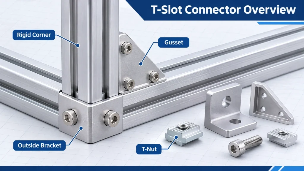
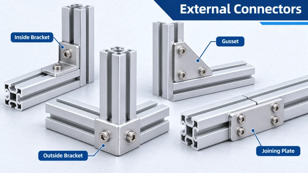
External T-Slot aluminum extrusion connectors mount on the outside faces and clamp through the slot with a bolt and nut. They need no drilling, tapping, or counterboring, can be repositioned repeatedly, and stay visible. They suit prototypes and frames that will be reconfigured, losing only on concealed appearance and extreme torsional stiffness.
Corner Brackets and Joining Plates
Corner brackets handle joints at an angle, and the variants are not interchangeable.
| Fitting | Rigidity | Best Fit |
| Inside corner bracket | Moderate | Enclosures where appearance matters |
| Outside corner bracket | High | Guards, load-bearing corners |
| 45 degree bracket | Moderate | Braces, chamfered frames |
| Adjustable angle bracket | Low to moderate | Odd angles |
| End-to-end joining plate | Moderate to high | Long beams, shipped frames |
| T and cross plate | Moderate | Cross members, shelf grids |
The inside bracket is nearly invisible but works with a short lever arm, so it should not carry the load-bearing corners of a tall frame. Splices on two or four faces are far stiffer than one, and a T plate adds a cross member without cutting the beam.
Gussets and Reinforcement Plates
A gusset is a corner bracket with a triangular web that transfers load diagonally rather than along the bolt axis, which makes it effective against racking, the sideways collapse that destroys square frames.
Put gussets on the corners carrying the longest span, since they see the largest moment, and mount them in the plane of the racking load. Gusset the bottom corners too if the frame will be lifted. Wall thickness then decides how much of that load the profile takes, and it is fixed by how the extrusion die is built.
Internal Connectors: Concealed and High-Strength
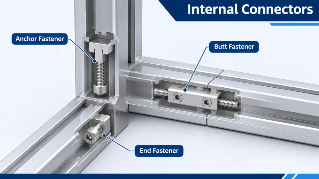
Internal connectors install inside the profile cavity and pull the joint together from within, leaving no external hardware visible. They give flush faces, higher torsional rigidity than most external brackets, and a clean surface for panels, but they need machining such as end tapping or counterboring. They suit production builds with a fixed joint design and planned machining.
On a frame built twenty times, machining amortizes and position comes from the machined feature rather than bracket alignment. Such a joint is stiffer than an external bracket because the fastener pulls against the profile wall, but it does not behave like a welded corner, which fuses two profiles into one section; matching welded construction needs a structural calculation. Because each fastener seats against the cavity, its size and wall thickness decide whether one fits, and both come from the hollow profile dies the section runs on.
Anchor and Butt Fasteners
Anchor fasteners are the strongest internal option. The body seats into a machined cavity and bears against the profile walls, resisting vibration loosening, with double anchors engaging both sides where a single one is marginal. Butt fasteners draw two ends together with a cam and bolt, suit tight spaces, and demand accurate counterboring, since a shallow bore cuts cam travel and leaves the joint slack.
End Fasteners and Central Connectors
End fasteners create a hidden 90 degree joint with a wing clip and screw: one profile is end-tapped and the mating one gets an access hole, whose visibility is the aesthetic cost. Central connectors position anywhere along the adjoining face, which suits adjustable sub-assemblies.
Selecting the Fastener Interface
Every family reaches the profile through a nut in the slot, and the nut type controls how fast the joint builds and how well it holds.
| Nut Type | Insertion Method | Best Use |
| Slide-in T-nut | Slides from the profile end | Assemblies with open ends |
| Drop-in T-nut | Drops in and rotates to lock | Retrofits, closed ends |
| Roll-in T-nut | Rolls in from the slot side | Panels added later |
| Spring-loaded T-nut | Held by a spring | Overhead work |
Button head screws give a low profile near panels, socket head screws allow higher torque, and countersunk screws suit flush faces. Check bolt length against fitting thickness plus nut engagement, because an over-long bolt bottoms out and applies no clamp load while feeling tight.
How to Join a T-Slot in Aluminum: Step by Step
Joining a T-slot in aluminum means preparing the ends, placing hardware in the slot, assembling finger-tight, checking squareness, and then tightening in a cross pattern. Sequence matters: assemblers who tighten each corner fully before checking square lock the frame out of alignment and must loosen everything to recover.
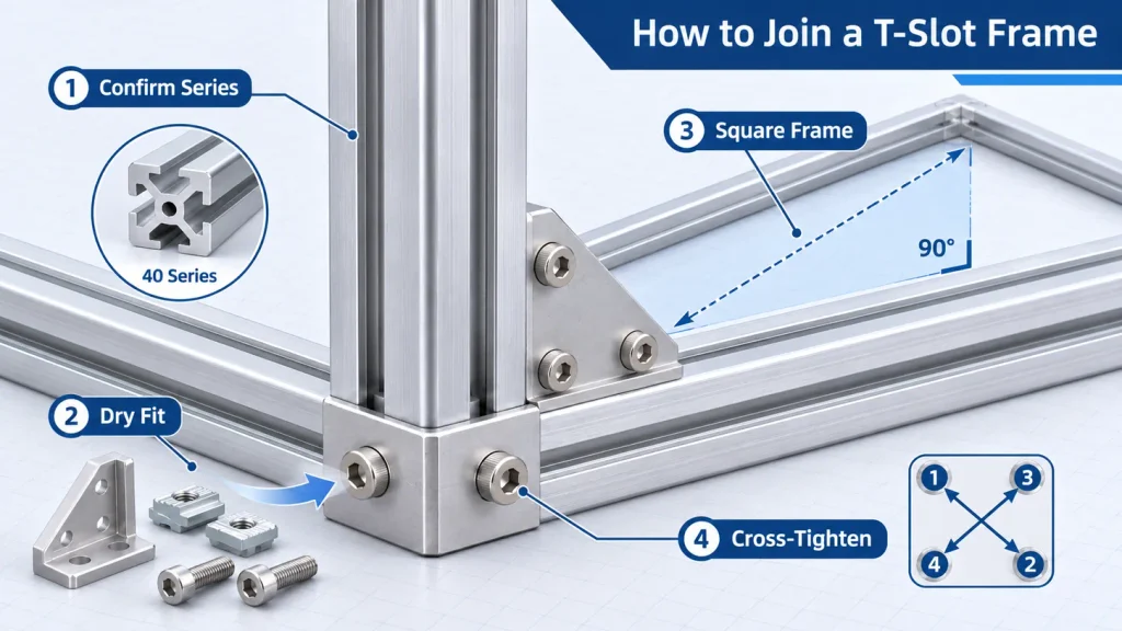
- Confirm the series. A bracket that seats loosely is the wrong series, not a defective part.
- Cut, deburr, and clean the slot. Burr-free ends are mandatory, and chips or lubricant change the friction torque assumes.
- Place the nuts and dry fit. One nut per bracket hole, a centimeter or two from the joint.
- Assemble finger-tight. Thread by hand first; a cross-threaded aluminum nut is unrecoverable.
- Square and tighten. Equalize both diagonals, then torque opposite corners in two or three passes. Brace spans beyond one meter.
Squaring and Torque Control
Squareness is the best indicator of assembly quality, so diagonals must be equal; more than a couple of millimeters over a one meter frame shows up as racking once loaded.
Torque control is where assemblies fail silently. Aluminum threads strip at lower torque than steel in a steel boss, and any published figure is valid only for one combination of bolt class, nut material and engagement length, connector stiffness, and thread condition, so do not lift one from a general article. Lubrication does not simply raise preload; it changes the friction the torque-to-preload ratio assumes, so the same reading yields a different clamp force. Use a calibrated tool, follow the connector supplier’s torque spec, and confirm on a trial joint that clamp force is reached without thread deformation or flange marking. Other clamping methods are covered in how to connect aluminum extrusions.
Common Assembly Mistakes
| Mistake | Symptom | Correction |
| Skipping deburring | Bracket will not sit flat, joint gaps | Deburr ends and slot edges after cutting |
| Tightening each corner completely | Square on the bench, racks under load | Finger-tight assembly, square, then cross-pattern torque |
| Using a bracket from the wrong series | Loose fit, nut rotates out under load | Verify slot width and series before assembly |
| Over-torquing aluminum nuts | Threads strip, joint loosens in service | Calibrated tool and the supplier’s torque value |
| Long unsupported spans | Visible sag or vibration | Add cross bracing or reduce span |
| Mixed bolt lengths | Bolt bottoms out, no clamp load | Verify engagement per joint thickness |
Load Capacity, Stiffness, and When a Bracket Is Not Enough
A single external corner bracket suits light frames and short spans but becomes the limiting factor as span, cantilever, or lateral load grows. The upgrade path runs from one bracket to two on the joint, then to gussets or joining plates, then to internal connectors, each step adding stiffness faster than a larger profile.
Deflection is beam bending plus joint rotation, and on short spans rotation dominates, which is why a larger profile often costs more and helps less than a second fitting.
| Condition | Weakest Element | Upgrade |
| Span under 600 mm, light panels | Joint rotation | Single inside bracket per corner |
| Span 600 to 1200 mm | Racking | Inside plus outside bracket, or gussets |
| Cantilever beyond 300 mm | Bolt tension at fixed end | Gusset plus joining plate |
| Continuous vibration | Preload loss | Locking nuts or anchor fasteners |
| Shipped or lifted frame | Bottom corners | Gussets below, four-face splices |
| Enclosed machine cell | Concealed look, rigidity | Internal anchor fasteners |
Two limits apply regardless of hardware. Keep cantilevers short, since a high static rating still deflects at the end of a long arm, and respect wall thickness, because a thin flange deforms before useful preload. Heavy-duty frames are therefore a tooling question too: extrusion die accuracy sets wall consistency, while ISO 898-1 property classes define the proof loads.
Choosing a Connector by Application
The sections above describe what each fitting does; this table starts from the requirement.
| Application | Recommended Connector | Main Consideration |
| Light-duty frame, short span | Inside corner brackets | Fast assembly, no machining |
| Heavy-duty frame or machine base | Outside brackets plus gussets | Joint rigidity governs deflection |
| Concealed joints on a visible product | Anchor or end fasteners | Needs end tapping at order stage |
| Structure that will be reconfigured | External brackets, drop-in nuts | Joints can move repeatedly |
| Adjustable or angled joints | Adjustable angle brackets | Lower rigidity, verify the load case |
| Long-span frame with cross members | Joining plates at T and cross junctions | Plate stiffness and bolt count |
| High-vibration environment | Internal anchors, locking nuts | Preload retention over time |
| Panel or guarding frame | Standard brackets plus panel strips | Slot width caps panel thickness |
| Volume production, fixed design | Internal connectors, machined in | Machining amortizes, position repeatable |
Accessories That Complete a T-Slot Frame
Extruded aluminum T-slot profiles accept a broad accessory range in the same channel used by T-Slot aluminum extrusion connectors: hinges, leveling feet, panel strips, slot covers, end caps, and cable clips. Each mounts without new holes, but accessories load the same flanges as joints, so plan both together.
| Accessory | Selection Note |
| Hinges | Match rating to panel mass |
| Pivot joints | Size for range of motion |
| Leveling feet | Match thread to the end tap |
| Casters | Check rating against frame weight |
| Panel strips | Must match panel thickness |
| Slot covers | Firm snap fit, sized by series |
| Cable clips | Clear of moving joints |
Specifying Connectors for Volume Production
For production runs, connectors should be specified with the profiles rather than picked from a catalog afterward. Designed as one system, slot geometry, wall thickness, and interface put machining into the order, and every unit reproduces the same rigidity.
The usual failure is not a bad connector but a sourcing mismatch, where profile and fitting each sit inside their tolerances yet do not seat.
- Tie the interface to profile design. Decide external or internal before the die is cut, since internal joints may dictate cavity size.
- Validate with a joint sample. Assemble a corner at rated torque, then check squareness retention after a load test.
- Put torque and sequence on the drawing. Instructions held in a person’s memory do not survive staff turnover.
Questions Worth Asking a Supplier
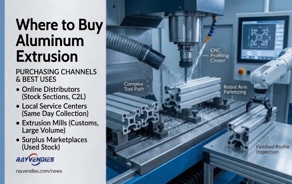
Four questions separate a source that stocks hardware from one that can carry a design. Can slot geometry be documented per section with quoted lip thickness and depth? Can the profile and joint preparation ship in one order, with end tapping scheduled inside the extrusion run? Can a joint sample be tested at the intended torque before the run? And can the same source name the right nut and bolt for each section, including custom slot dimensions? A supplier that matches connectors to the profiles it extrudes answers the last before it is asked.
Answering all four from one drawing removes that risk, which is why fixed-design projects consolidate profile, machining, and hardware into one order. That consolidation is what custom extrusion tooling is built for.
FAQ
Can connectors from one supplier be used with profiles from another?
Often, but only when series, slot width, and lip thickness match closely enough to register on the flange. Test a trial joint at rated torque, because corner radii vary between producers in one series.
Do T-slot connectors loosen over time?
Friction-clamped joints lose preload under sustained vibration, which is why machine frames specify locking hardware, threadlockers, or internal connectors that bear on the profile walls.
Can a T-slot frame be rebuilt in a different configuration?
Yes, if the original joints used external connectors or reusable internal hardware. Frames built with threadlocker or cavity-deforming connectors may need new nuts, but the profiles stay reusable.