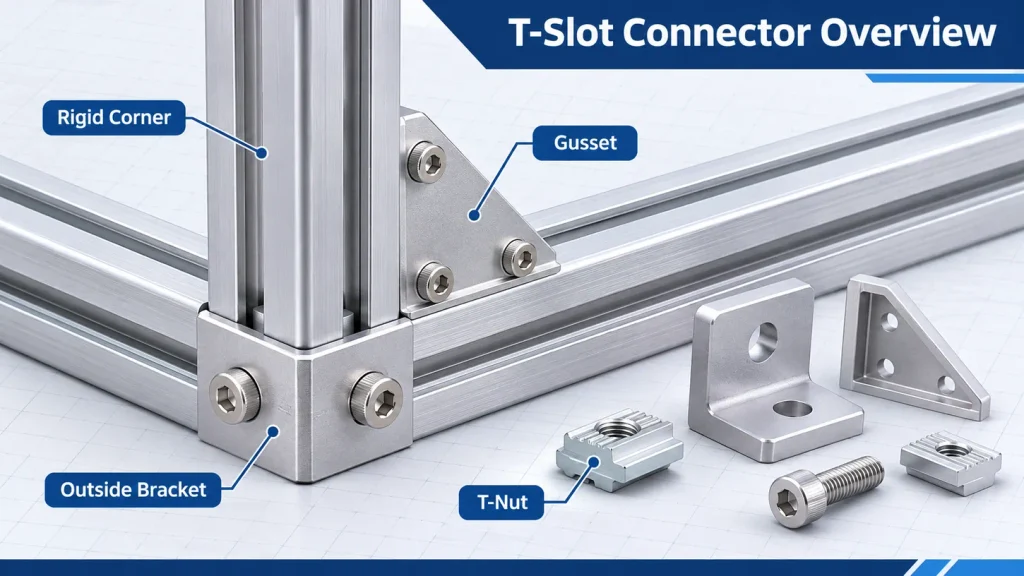
Specifying an aluminum T-slot frame means crossing the same gap: dozens of profile codes in the catalog, slot openings drawn in tenths of a millimetre, and accessory bins sorted by series.
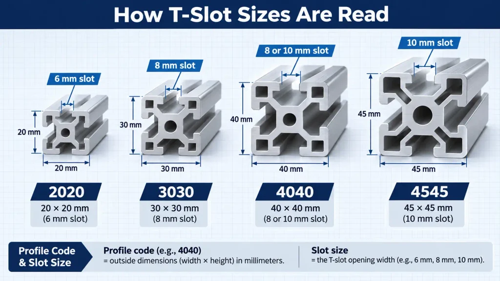
The size of an aluminum extrusion t-slot is defined by two separate numbers: the profile’s outside dimension, which gives the series name such as 2020 or 4040, and the slot opening width, which decides whether a T-nut and bolt will fit. Series size controls stiffness and load; slot width controls hardware compatibility. Both must be confirmed before anything is ordered.
This reference works through both numbers, from reading a code to checking tolerance on delivery.
What the Numbers in a T-Slot Size Actually Mean
Every T-slot profile code encodes its cross-section in millimetres or inches, and none states the slot width. A 4040 is 40mm by 40mm with an 8mm or 10mm slot depending on who made it. The outside dimension tells you how stiff the profile is; only the drawing tells you what fits inside.
The pattern is usually width then height, sometimes with letters for features such as a closed face. Slots normally run on the faces used for panel or bracket attachment.
Reading a Profile Code
| Profile Code | Section Size | Slots | Typical Slot Width | What the Code Tells You |
| 2020 | 20 x 20 mm | 4 | 6 mm | Smallest common section |
| 2040 | 20 x 40 mm | 4 or 6 | 6 mm | Same hardware as 2020 |
| 3030 | 30 x 30 mm | 4 | 8 mm | More stiffness, same slot |
| 4040 | 40 x 40 mm | 4 | 8 or 10 mm | The code settles nothing |
| 4080 | 40 x 80 mm | 6 | 8 or 10 mm | Long span beams |
| 4545 | 45 x 45 mm | 4 | 10 mm | M8 and M10 hardware |
Dimensions vary between producers, so treat this as a starting point. For one series in detail, read the published figures for 2020 Aluminum Extrusion Dimensions.
Why Slot Width Is the Number That Matters Most
A slot too narrow cannot be opened on site without damaging the anodised surface, and one too wide leaves a T-nut loose enough to rotate.
Typical T-Slot Aluminum Extrusion Sizes and Specifications
Metric systems are normally grouped by section size in millimetres, and each group tends to be offered with one slot width: 6mm with the 20 series, 8mm with the 30 and 40 series, and 10mm with 45 and above. Those are catalog patterns, not a standard every mill follows. Moment of inertia rises steeply between groups, so one step up in section buys far more stiffness than weight.
Manufacturer and System Variation
The table describes typical catalog practice, not a specification. The same nominal section comes with different slot widths, so a 4040 exists in both 8mm and 10mm versions. Wall thickness varies with the variant, which changes weight and moment of inertia, and accessory geometry is proprietary, so brackets match a slot drawing rather than a nominal size. A specification should therefore carry the manufacturer, the part number and the slot width.
| Series | Common Sections | Typical Slot Width | Typical Duty |
| 20 | 20×20, 20×40 | 6 mm | Fixtures, small enclosures |
| 25 | 25×25, 25×50 | 6 mm | Compact fixtures |
| 30 | 30×30, 30×60 | 8 mm, occasionally 6 mm | Guards, displays |
| 40 | 40×40, 40×80 | 8 or 10 mm | Machine frames |
| 45 | 45×45, 45×90 | 10 mm, occasionally 8 mm | Heavy guarding |
| 50 | 50×50, 50×100 | 10 mm | Gantries |
| 60 | 60×60, 60×120 | 10 mm | Machine bases |
| 80 | 80×80, 80×160 | 10 mm, often twin | Transport frames |
Weights and core holes are left out deliberately. They depend on wall thickness and internal ribbing rather than the series name, so ask for the section drawing with area and moment of inertia and calculate from those.
Light Sections: 20 and 25 Series
The 6mm slot caps these sections at roughly M5 hardware, and a bracket small enough for M5 cannot transmit much load into a corner joint. They suit printer frames, sensor mounts and small enclosures, and stop being right once a motor is mounted.
The 30 and 40 Series Working Range
Both series are usually offered with an 8mm slot, which allows 40mm columns with 30mm cross members. The shared slot hides a large stiffness gap, since a 40mm section carries several times the moment of inertia of a 30mm one. Passing a nut across that boundary is usually safe; assuming the profiles behave alike is not. Some producers also offer 4040 in 10mm, so two frames drawn to identical nominal sizes can reject the same bracket.
Heavy Sections: 45 Series and Above
Above 45mm the slot commonly opens to 10mm with M8 and M10 fasteners, and sections past 50mm often use twin slots. Connections become stiffer than the profiles they join, so the question shifts to deflection. The limits of a small frame are worked through under 2020 Aluminum Extrusion Strength.
Metric Versus Fractional: Two Systems That Look Alike
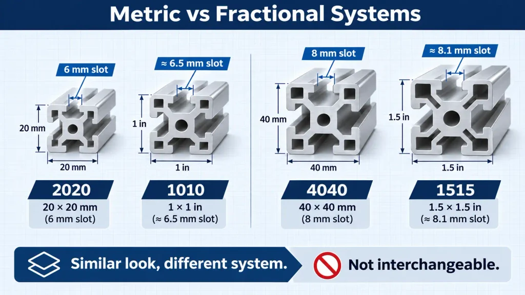
Fractional systems use inch sections such as 1 inch and 1.5 inch; metric systems use 20, 30, 40 and 45mm. The numbers look similar and are not, and neither hardware nor T-nuts transfer. A 1.5 inch profile measures 38.1mm, close to but incompatible with a metric 40 series.
The Series Names That Appear in Both Systems
| Code | Fractional Meaning | Metric Meaning | Difference |
| 1010 vs 2020 | 1 inch square, slot 6.5 mm | 20 mm square, slot 6 mm | Different section and slot |
| 1515 vs 4040 | 1.5 inch square, slot 8.1 mm | 40 mm square, slot 8 mm | 38.1 mm against 40 mm |
| 2040 | 2 x 4 inch, slot 6.5 mm | 20 x 40 mm, slot 6 mm | 30 mm apart |
| 3060 | 3 x 6 inch, slot 8.1 mm | 30 x 60 mm, slot 8 mm | 46 mm apart |
Fractional 10 series with a slot near 6.5mm matches the metric 20 series in slot width and not in section size, so a nut may enter and still be wrong. The definition of the 10 Series Aluminum Extrusion helps when a drawing carries a 10 prefix.
How to Tell Which System You Already Own
Measure the slot opening: near 6mm suggests a metric 20 series, near 6.5mm a fractional 10 series, near 8mm a metric 30 or 40 series or a fractional 15 series. Then measure from the outside face to the slot centre, where a clean half or three-quarter inch points to fractional geometry and 10, 15 or 20mm to metric.
Matching T-Slot Size to Load and Span
Section size is chosen by span and load together, not by load alone. An aluminium beam deflects with load and with the fourth power of its span, so doubling a span increases deflection sixteen times. A 40 series beam adequate at one metre is not adequate at two.
Preliminary Span Guidance
The table below is a starting point for first estimates only. It assumes a uniform static load, a simply supported member, no bracing, and a heavy or standard wall variant. Span cannot be read off a series name, because the same 4040 is sold in several wall thicknesses and internal geometries whose moment of inertia differs substantially. Any structure that carries people, moving equipment or safety guarding needs a calculation from the supplier’s section data.
| Series | Typical Preliminary Span | Usual Application | Where the Estimate Fails |
| 20 | Under about 400 mm | Fixtures | Moving or point loads |
| 30 | Under about 700 mm | Guards | Motor mounts |
| 40 | Under about 1000 mm | Machine frames | Spans past 1.5 m unbraced |
| 45 | Under about 1500 mm | Heavy guarding | Gantries |
| 50 and above | Often beyond 2 m | Machine bases | Section price |
Check against permissible deflection rather than strength: an aluminium section reaches its deflection limit well before yield.
A Worked Deflection Check
Centre deflection of a simply supported beam under uniform load is five times the load per unit length times the span to the fourth power, over 384 times the elastic modulus times the moment of inertia.
Span dominates. Doubling the span multiplies deflection by sixteen, not four, which is why a section that looks generous at one metre sags visibly at two. Section enters linearly through the moment of inertia, and that number comes from the supplier drawing rather than the series name. Aluminium’s elastic modulus of roughly 69 to 70 gigapascals, about a third that of steel, means a beam of identical section and load deflects about three times as far, according to published modulus of elasticity data for aluminium.
Three mistakes ruin the estimate. Choosing by weight per metre fails because two sections of similar mass can differ greatly in moment of inertia. Ignoring load direction fails because a profile stiff vertically may be flexible under a horizontal load. Treating a cantilever as a supported beam fails because deflection at the free end grows far faster.
Hardware Compatibility by Slot Size
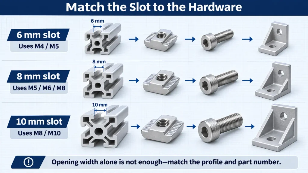
The slot opening sets the T-nut, the T-nut sets the bolt thread, and the thread sets the bracket. Breaking that chain gives a part that will not enter the slot, or a joint that cannot be tightened to the load the profile carries.
| Series | Slot Width | T-Nut Size | Bolt Thread | Bracket |
| 20 | 6 mm | 20 series | M4, M5 | Light die-cast |
| 30 | 8 mm | 30 series | M5, M6, M8 | Die-cast |
| 40 | 8 mm | 40 series | M6, M8 | Die-cast or machined |
| 40 | 10 mm | 40 series wide | M8, M10 | Machined gusset |
| 45 and above | 10 mm | 45 series | M8, M10 | Heavy gusset |
Why the Same Slot Width Does Not Guarantee a Shared T-Nut
A matching opening is necessary and not sufficient. Five dimensions decide whether a nut seats and clamps.
- Opening width. The nut must pass the mouth, which is the test most buyers check.
- Slot depth. A nut deeper than the slot stands proud of the face; a shallower one bears on the mouth instead of the shoulders.
- Shoulder width. Load runs through the internal shoulders, and a nut narrower than the shoulder contact area dents the profile.
- Nose or collar height. Drop-in nuts register on a nose that sits in the opening, and a nose taller than the slot prevents the nut seating flush.
- Thread size and type. A thread larger than the nut shoulder can carry is the limiting case, and mixed metric and unified threads rule out a shared bolt.
Shoulder geometry sits inside these five, because the internal angle and pocket shape differ between systems at identical nominal widths. A nut can enter, slide and clamp while bearing on the wrong surface, which surfaces later as a joint that loosens under vibration. Match nut and profile by part number, and test one joint on an offcut before ordering the balance.
Tolerances and Cross-Brand Compatibility
A nominal slot width is not a measured one. Commercial tolerances on a 6mm or 8mm slot are typically plus or minus 0.1mm or looser, so two producers working to different standards can both be correct while accepting the same nut differently. Fit is decided by tolerance, not by the nominal figure.
What Tolerance to Ask For
European practice follows EN 755-9, which sets tolerances on dimensions and form for extruded profiles within a circumscribing circle up to 800mm and treats a dimension across an enclosed hollow more generously than one across solid metal. A slot partly bounded by walls falls closer to the hollow case and is quoted wider than outside faces. The full picture sits in the site account of Aluminum Extrusion Tolerances. Specify the class you need rather than the tightest, and confirm it on a sample.
How T-Slot Sizing Is Fixed at the Die Stage
The slot is not cut afterwards; it is formed by metal flowing around a shaped opening in the die, so shoulder angle, pocket depth and opening width are fixed by die geometry. A slot opening through one side is formed in a flat die, while a slot creating an enclosed hollow needs metal fed around a mandrel or re-welded inside the die, the family covered by Hollow Aluminum Extrusion Dies. Sections of 20 to 30mm typically run on presses of 600 to 1000 tonnes; larger ones need capacity matched to the circumscribing circle.
Sizing for Assembly and Cutting
Profile size changes the cut and the joint more than most buyers expect. A 45mm section needs a blade and clamping setup that will not distort a hollow, and cut length must allow for kerf and end machining.
A saw that suits a 20mm section leaves a heavy burr on a 45mm one, and a raised edge stops brackets sitting flat. Internal connections are drilled and tapped, which removes load-carrying material. Bolt length needs checking: bracket thickness plus nut height against the distance from bracket face to the pocket bottom. Connection methods are set out in this guide to How to Connect Aluminum Extrusions.
A Practical Sizing Workflow
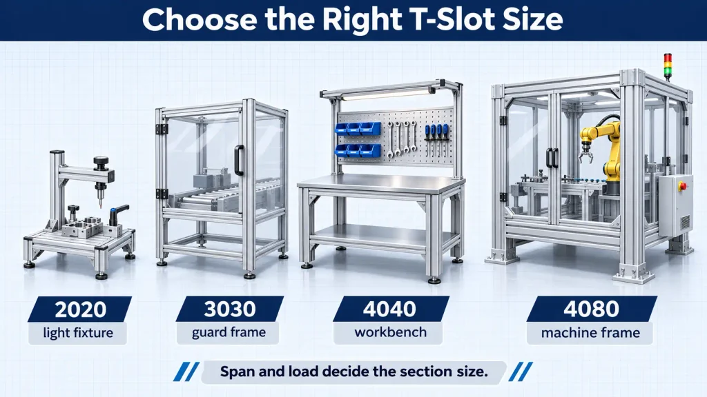
Sizing a frame reduces to five decisions in a fixed order: measurement system, slot width, section size for span and load, tolerance, then hardware. Taken out of order, any step forces the earlier ones to be revisited.
The table is an illustration of that order applied to common projects, not a substitute for checking the longest span.
| Application | Initial Choice | Main Consideration |
| Desktop fixture, small enclosure | 2020 | Lightest section taking M5 hardware |
| Guard frame, display structure | 3030 | 8mm slot, hardware shared with 40 series |
| Workbench, assembly table | 4040 | Rigidity under distributed tool load |
| Machine frame, robot cell | 4040 or 4080 | Depth in the bending direction |
| Industrial gantry | 4080 or 4590 | Span first, section second |
| Structural frame over 2 m | 5050 and above | Deflection governs, not stress |
One question is worth settling before ordering: whether a standard section will do, or whether slot position, opening or pocket depth must move. A T-slot section deviates from the catalog only when a die is cut for it, and those projects run through OEM ODM Extrusion Die Services, where drawing, alloy and press are fixed together.
FAQ
These cover what the decisions above leave open: nut interchangeability, why a slot measures differently from its label, and when a standard section stops being the answer.
Can T-Nuts From 2020 and 4040 Profiles Be Swapped
No. A 2020 profile has a 6mm slot and a nut proportioned for it, while a 4040 profile has an 8mm or 10mm slot with a taller shoulder and larger thread. A 40 series nut will not enter a 6mm opening, and a 20 series nut dropped into a 40 series slot sits too low against the shoulders to clamp.
Why Does My 6mm Slot Measure About 6.2mm
Two reasons. The nominal slot width refers to the opening designed to admit a compatible T-nut or sliding fastener, and the actual opening is usually made slightly wider so that nut enters without binding. Separately, extrusion tolerance permits variation along the length, so a small difference between nominal and measured is normal. Whether a particular reading is acceptable depends on the tolerance band in the supplier’s drawing, so check against that document rather than against the nominal figure alone.
When Should I Commission a Custom T-Slot Section
When the catalog cannot deliver the slot position, opening width, pocket depth or secondary features the design needs, and volume justifies a die. Five situations justify it:
- Custom slot width, where a standard opening will not accept the intended fastener
- Custom section dimensions between catalog sizes
- Slot positioning on faces the catalog does not offer, or at a non-standard spacing
- Internal cavities for cable routing, weight reduction or heat dissipation
- Tooling for an OEM program, from drawing to sample to production
For a few hundred metres of a modified standard section, machining a standard profile is usually cheaper; past that, a dedicated die pays for itself in fewer secondary operations and a repeatable slot.