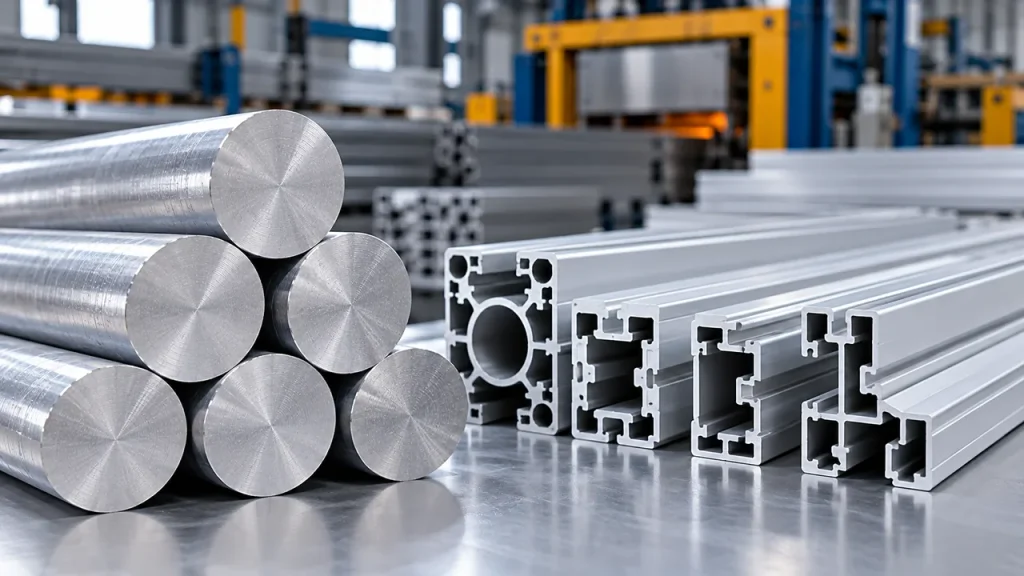
T-slot profiles are bought like fasteners: picked from a catalogue, cut to length, and bolted together with standard nuts. That works until a nut binds, a frame will not sit flat, or a slot measures right at both ends and pinches in the middle. Then it becomes a tooling problem, decided months earlier on a die drawing.
T-slot aluminum extrusion die design is the practice of shaping a die so that a cantilevered tongue forms the slot while the surrounding metal reaches the bearing at a matching speed, then holding the slot opening, twist, and straightness inside limits that the actual T-nut can tolerate. The die fixes the cross-section and the flow balance, but quenching and stretching decide how much of that geometry survives. Sections are grouped into series by outside dimension and slot spacing, standard profile tolerance and assembly tolerance are separate requirements, and manufacturing turns on tongue machining, EDM, heat-treat distortion, and first-article measurement.
The sequence below starts with the feature that causes most of these failures.

Why a T-Slot Section Is a Die Design Problem Before It Is a Profile
A T-slot is difficult because the slot is formed by a tongue of die steel supported on one side only. Every other feature is shaped by a bearing backed by solid steel, while the slot is shaped by a projection that must resist pressure, conduct heat, and hold position for the whole run. Slot width, depth, and squareness are die-stiffness outcomes before they are drawing dimensions.
The Anatomy of a T-Slot Section
A T-slot has six features: the mouth at the face, the neck behind it, the flange that forms the undercut a nut turns into, the base that closes the cavity, the core wall between slot and outer face, and the corner radii and datum faces the shop measures.

The envelope and wall thicknesses come from the die aperture; the mouth, neck, and undercut come from the tongue. Because aluminum extrusion dies are cut around one slot geometry, a die built for 6 mm cannot be opened to 8 mm and behave like one designed for 8 mm.
Semi-Hollow or Hollow: Which Die a T-Slot Actually Needs
The shorthand that an open slot means a semi-hollow die is a starting point, not a classification. T-slot features may require semi-hollow die design when their partially enclosed geometry creates a high tongue ratio, while profiles containing fully enclosed cavities typically require hollow-die tooling such as a porthole or bridge die. Extruders screen the first case on the ratio of void area to gap width squared.
A section carrying an external slot and an internal cavity needs both forming methods in one die, which is where hollow aluminum extrusion dies become unavoidable. The mandrel leaves a weld line, and where that line sits is a design decision.
How the Die, Not the Drawing, Sets Slot Function
Bearing length controls flow: a longer bearing slows a region, a shorter one lets it run, and the goal is one exit speed everywhere. A slot wall thinner than its neighbours runs fast unless its bearing is balanced, which is where wall thinning, die lines, and distortion begin.
Tongue deflection drifts with die temperature and bearing wear, so slot width moves gradually rather than failing suddenly. The Aluminum Extruders Council reference on dies and tooling covers these relationships in detail.
Aluminum Extrusion Profile Types and the Section Sizes Buyers Compare
Extruded sections fall into solid, semi-hollow, and hollow, and the group sets the die family, which sets tooling cost, lead time, and first-article risk. T-slot profiles sit mostly in the semi-hollow and hollow groups. Nominal size is given by a series designation, but the series number alone does not tell a buyer the slot opening, the cavity depth, or which nut will fit.
What Standard T-Slot Profiles Cover
Single-slot and two-slot sections serve edge mounting, four-slot squares serve general framing, rectangular sections suit gantry beams where bending runs one way, and panel-ready sections add a glazing groove. Each extra slot face adds forming features and bearing area, raising complexity; press pressure follows section area, extrusion ratio, alloy, and flow path, not slot count.
The die family follows void geometry, not application. Two sections of the same nominal size need different tooling when only one carries a closed cavity.
Standard Sizes and Slot Series
Series designations are not one global system, and treating them as one is the most common ordering error. Inch and metric ranges both use short numbers that do not mean the same thing. The series number relates to outside dimension and slot centre spacing; the slot opening is separate and must be confirmed on its own. Sections labelled 60 mm or 80 mm may be individual profile sizes rather than independent series.
| Series | Common example | Confirm before ordering |
| 15 Series, inch based | 1.5 in by 1.5 in | Inch slot geometry and connectors, not a metric 15 mm system |
| 20 | 20 by 20 mm | Slot opening, nut size, cavity depth |
| 25 | 25 by 25 mm | Slot opening and cavity dimensions |
| 30 | 30 by 30 mm | Nut size and slot base depth |
| 40 | 40 by 40 mm | Slot form, wall thickness, connector series |
| 45 | 45 by 45 mm | Slot opening and hardware compatibility |

Two suppliers can offer a nominal 40 by 40 mm with different cavity dimensions, and outside size sets the circumscribing circle that decides press options and cavities per die.
Die Design Guidelines for T-Slot Sections
The guidelines that matter most for T-slot tooling keep the tongue alive and keep metal arriving at the slot at the same speed as the rest of the section. Blunt the tongue tip rather than tapering it to a knife edge, radius every internal corner, keep wall transitions gradual rather than stepped, balance the section about its own axes, and put only continuous features into the extrusion. Where a guideline conflicts with function, the alloy, the section, and the die maker’s manufacturability review decide the final geometry.
Geometry Rules That Protect the Tongue
A slot mouth cannot be narrowed indefinitely for a given depth. As the depth-to-opening ratio grows, the tongue becomes a thin blade in compression and bending, and the section moves toward the semi-hollow limits above. Where a narrow mouth is required, reduce slot depth, widen the mouth, or move the feature to a secondary operation.
Sharp corners are the other failure mode. Design guidance suggests inside corners no smaller than about 0.015 in and outside corners no smaller than about 0.020 in, with knife edges rounded and tapers used generously. These values favour clean extrusion and die life, but they are not acceptance criteria for every slot cavity.
Wall Thickness and Symmetry Rules
Uniform wall is the most effective habit for dimensional stability, because equal walls cool at equal rates. Where a thickness change is unavoidable, blend it with a radius or taper rather than a step, since a step creates a flow discontinuity that surfaces as a die line or a tear.
A 2:1 ratio between adjacent wall thicknesses is a working target, useful as a preliminary design check rather than a standard every section must satisfy. The acceptable ratio depends on the alloy, the absolute wall thickness, where the walls sit, and what the die can support.
Symmetry is the second habit: a section balanced about its own axes cools evenly and holds dimensions predictably.
Drawing Practice That Prevents Rework
The drawing should separate what extrusion can deliver from what has to be machined afterwards. Slot opening, slot depth, and slot position belong in the extrusion requirement when they are functional; cross holes, pockets, tapped ends, and tight mounting faces belong in the machining requirement.
Reference functional dimensions to datums that mean something to the assembler, usually the slot face or centreline rather than an outside edge. State alloy and temper, cut length, surface treatment, and inspection scope, and give any cited standard its edition number.
When a Modular Die Makes Sense
Slot width drift is the slow failure mode of any T-slot die. Bearing wear and repeated correction both move the mouth, and once it leaves the functional band the die has to be recovered.
Detachable modular extrusion dies change that calculation, because the tongue and bearing insert can be replaced without disturbing the die body. For a family of sections that share an envelope and differ only in slot geometry, modular construction pays back on the first correction.
Tolerances That Decide Whether the Slot Actually Assembles
Standard extrusion tolerance describes what the process normally delivers across a profile. Assembly tolerance describes what a specific nut, bracket, or slider needs in order to fit. A profile can meet general extrusion tolerances and still fail the fit requirements of a particular T-nut or connecting bracket, which is why the slot opening, the twist, and the straightness have to be treated as functional dimensions rather than as part of a blanket tolerance block.
| Parameter | What it controls | How it surfaces in assembly |
| Profile outside dimension | Envelope and wall position | Brackets sit proud, diagonals do not square |
| Wall thickness | Local stiffness and thread depth | Tapping strips, fasteners pull out |
| Slot opening | Whether the nut enters and the slider runs | Nuts bind or drop through |
| Straightness | Bow along the length | Long frames rock, rails need shimming |
| Twist | Rotation about the section axis | Mating faces do not close, gaskets leak |
| Cut length and end squareness | Fit at the joint | Gaps at corner brackets, crushed slot ends |

Which Parameters Break Assembly First
There is no fixed ranking, because the dominant parameter follows the application. On a linear frame where a slider travels the full length, slot opening and slot consistency control whether the carriage moves freely. On a tall frame with long unsupported spans, straightness and twist decide whether the structure sits on four feet or two.
Name the failure the assembly cannot tolerate and control that parameter tightly. Blanket precision raises die cost, slows correction, increases scrap, and buys nothing the assembly can use.
Extrusion Tolerance Is Not Machining Tolerance
Extrusion reproduces a cross-section consistently but does not hold a feature created after the press. A mounting hole, pocket, or machined shoulder should carry its own tolerance, and the extrusion should only leave enough stock to create it. The sequence that works is extrusion, cutting, machining, then final inspection, with each step carrying its own limits.
Anodising and powder coating are applied after cutting and both consume slot clearance, so a slot that accepts a nut as bare aluminium may not accept it after a heavy build. Trial-fit finished samples with the actual hardware before releasing a batch.
Standards to Put on the Drawing
Tolerance tables scale with profile size and distinguish metal dimensions from space dimensions. A slot opening behaves as a space dimension rather than a metal dimension, which is why a general outside-dimension tolerance cannot simply be carried across to the slot. The Aluminum Association tolerance guidance explains how twist, straightness, flatness, and that distinction are measured, and the wider framework for aluminum extrusion tolerances applies the same logic across profile families.
Cite EN 755-9 for dimensional tolerances of extruded profiles or ASTM B221 for aluminium-alloy extruded shapes, and write the edition number rather than the words “as per standard”. Where a slot dimension is functional, quote the requirement explicitly so the extruder is not left to choose.
Manufacturing: From Die Steel to Finished T-Slot Profile
T-slot die manufacturing is dominated by four operations that decide whether the slot comes out right: machining the tongue and its supporting web, burning the bearing and profile form with EDM using matched electrodes, controlling distortion through heat treatment, and correcting the die after trial until the slot measures inside its band. The press cycle then has to preserve what the die produced, which is why runout support and quench uniformity are checked against slot dimensions rather than outside size.

Making the Die: Tongue, Bearing, and EDM
The die body is normally cut from H13 tool steel. Rough machining removes the bulk of the aperture, and the profile form, bearing, and tongue detail are produced by EDM, because the undercut and the narrow neck cannot be reached by a rotating cutter.
Heat treatment comes next and moves the geometry. Quenching and tempering relieve machining stress but introduce distortion, and nitriding grows the surface slightly. The die maker compensates in the pre-treatment dimensions, then trial-runs on production alloy and corrects bearings and tongue until the slot lands inside its band.
Where Distortion and Wear Show Up
Die lines appear where flow was uneven across a bearing. Twist appears where the section was unbalanced and the quench pulled it unevenly. Slot width drift appears late in die life as the tongue and its bearing wear, which is why a die that passed first article can still reject nuts two years later.
First article should measure the slot at both ends and at mid-length of a full run. Check twist and straightness over the length the customer will actually use, because a profile that passes on a three-metre table can fail on a six-metre frame.
What to Include in a T-Slot Extrusion Die RFQ
Where the section is proprietary or the slot geometry has to change, OEM ODM extrusion die services are quoted against a drawing package rather than a catalogue number. That package should contain:
- A 2D section drawing or DXF/DWG file with the slot geometry dimensioned and its functional tolerance stated
- The series designation and a note on which hardware the slot must accept
- Alloy and target temper, since both affect flow and achievable tolerance
- A sample T-nut, bracket, or joining plate for the finished profile to be tested against
- Press and billet data, so the circumscribing circle and extrusion ratio can be checked
- Expected volume, cut length, surface treatment, and first-article acceptance criteria
Frequently Asked Questions
The three questions below cover cases that sit outside routine die specification work.
Can a T-slot profile be milled from solid bar instead of extruded?
It can, and for one prototype it is sometimes faster. Milling removes material, adds setup and deburring time, and leaves cut faces that differ from the mill finish. Past a small batch, a dedicated die is cheaper per metre and far more repeatable along a long length.
How long does a T-slot extrusion die last before it needs replacing?
Die life is measured in metres of good profile and depends on alloy, section complexity, bearing design, and correction frequency. The practical indicator is the correction interval: when a die needs bearing work more often to hold the same slot width, it is nearing replacement.
Why do T-nuts from different suppliers not fit the same nominal slot?
Because the series number describes outside dimension and slot spacing, not the slot opening. Two profiles of the same nominal size can differ in mouth width, cavity depth, and flange thickness, and coating build varies by supplier. Trial-fit a finished, coated sample with the intended hardware.