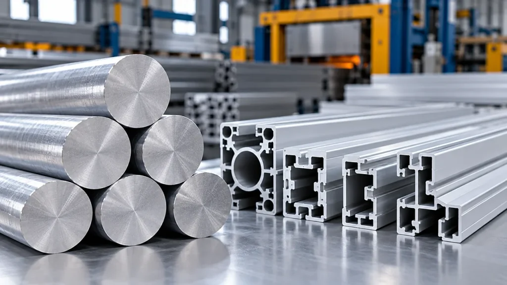
Aluminum extrusion is one of the most economical ways to produce long metal parts with a constant cross section. The process turns a heated aluminum billet into a finished profile in a single stroke of a press, which is why extrusions appear everywhere from window frames to solar racks. But a profile straight off the press rarely matches the dimensions, holes, or surface quality that a finished component needs. That gap is where machining comes in.
Aluminum extrusion machining is the set of secondary operations—cutting, milling, drilling, tapping, bending, and finishing—applied to extruded profiles so they reach final dimensions and assembly readiness. The extrusion press creates the profile shape; machining adds the local precision features, tight tolerances, and clean edges that the press cannot deliver on its own. Since every profile starts with a shaped opening, buyers who need a specific cross section often begin with custom aluminum extrusion dies before any machining is planned.
The rest of this guide covers the full manufacturing process step by step, the most common machining operations, joining methods, typical applications, and the cost factors that shape a machining quote.
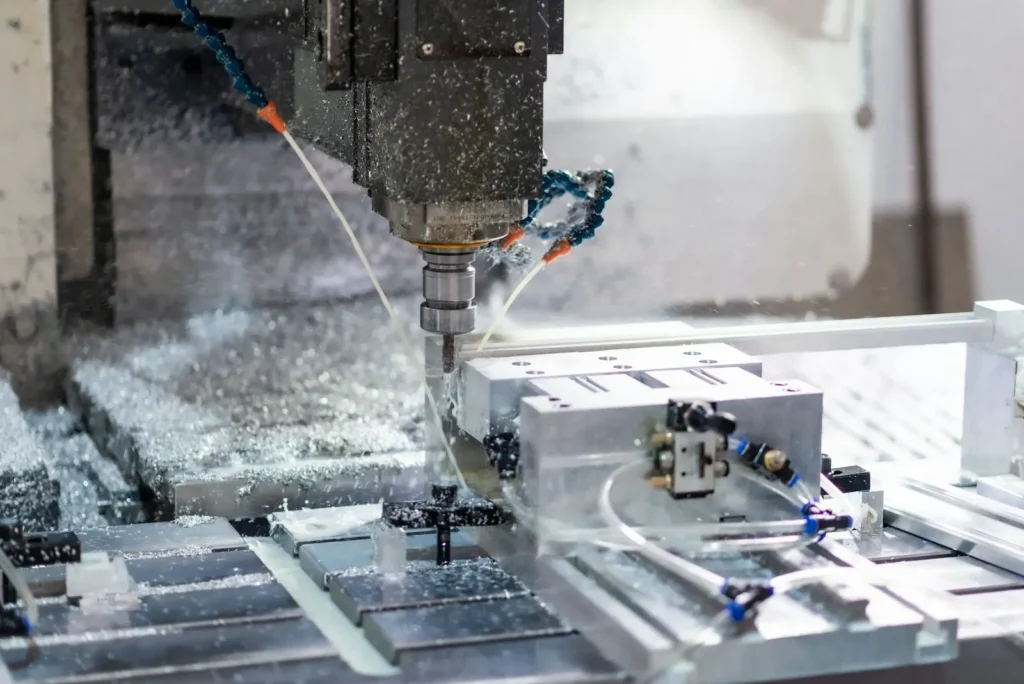
What is aluminum extrusion machining?
Aluminum extrusion machining covers every secondary cutting and material-removal operation performed on a profile after it leaves the press. The press produces a continuous shape with a fixed cross section; machining adapts that shape to a specific part, adding features and accuracy the extrusion process itself cannot hold.
The two processes are complementary rather than competing. The Aluminum Association describes extrusion as a plastic deformation process in which a solid cylinder of aluminum, the billet, is forced under compression through a smaller die opening, typically after preheating (Aluminum Association, Processing 101). That process excels at producing meters of consistent profile at low tooling cost per kilogram. Machining then handles the exceptions: a milled pocket here, a tapped hole there, and a precision-cut end that must mate with another component. Splitting the work this way keeps material costs low while still delivering tight local tolerances.
In practice, “aluminum extrusion machining” also includes fabrication steps that do not remove material, such as bending and joining. What ties them together is that they all happen downstream of the press and determine whether the profile can actually be assembled into a product.
How the aluminum extrusion manufacturing process works
A heated aluminum billet is forced through a shaped die by a hydraulic press, then cooled, stretched, cut, aged, and inspected before it reaches the machining floor. Understanding these steps matters for machinists because each one affects the condition of the profile they receive.
The standard sequence runs as follows:
- Billet and die preparation. The die is heated to promote stable metal flow, and the billet is cut to length and preheated to a temperature that suits the alloy.
- Extrusion. The billet is loaded into a container, and a ram pushes it through the die. The aluminum emerges as a continuous profile matching the die opening.
- Cooling. The profile runs out onto a table and is cooled with air or water, which fixes its metallurgical structure.
- Stretching and straightening. A stretcher pulls the profile to remove the twist and bow introduced during cooling.
- Cutting to work length. Profiles are sawn into manageable lengths, often around six meters, for handling and further processing.
- Aging. Profiles are aged in ovens or at room temperature to reach the specified temperature, such as T5 or T6.
- Inspection. Cross-section dimensions, straightness, twist, surface condition, and mechanical properties are checked against standard tolerance tables.
The shape a die can produce falls into three broad families. Solid profiles have no enclosed voids, such as angles, bars, and channels. Hollow profiles contain one or more enclosed openings, like tubes, and require a bridge or porthole die with a mandrel that shapes the internal void. Semi-hollow profiles sit in between, with a narrow gap that a semi-hollow die can still form. The die type affects wall thickness control and, downstream, how much machining support the profile needs.
For machining purposes, the key takeaway is that as-extruded profiles carry industry-standard dimensional tolerances that widen with profile size and wall thickness. Machining is what closes the gap between those general tolerances and the specific fit a design requires.
Common machining operations for extruded aluminum profiles
The most common operations are cutting to length, followed by milling, drilling, and tapping, with bending used where the design calls for curves or angles the die cannot produce. Each operation has its own tolerance range, equipment, and failure modes.
How to cut aluminum extrusion
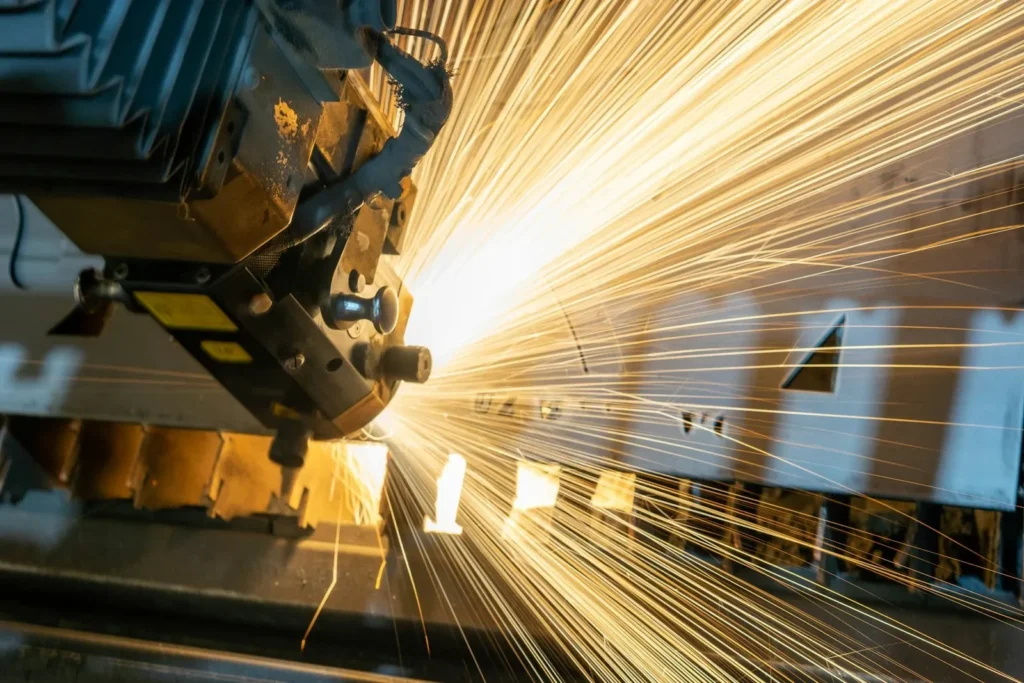
Cutting is the first and most universal machining step, because profiles arrive in long lengths that must be divided into part blanks. The method you choose determines edge quality, achievable tolerance, and heat input into the part.
| Method | Typical tolerance | Edge quality | Best for | Heat input |
|---|---|---|---|---|
| Cold saw | ±0.5 to ±1 mm | Clean, near-burr-free | High-volume straight cuts | Minimal |
| Miter saw with carbide blade | ±0.5 to ±1 mm | Good, light deburring | Angled cuts for frames | Minimal |
| CNC saw or routing | ±0.1 to ±0.3 mm | Excellent, consistent | Tight tolerances, repeat batches | Low |
| Waterjet | ±0.1 to ±0.2 mm | Smooth, no burr | Heat-sensitive or thin-wall profiles | None |
These ranges reflect common industry practice; individual shops quote tighter or wider depending on equipment and profile complexity. One method to avoid is the abrasive cutoff wheel. Friction heat can discolor anodized surfaces and leave a rough edge that needs heavy deburring. Clamping also matters: supporting the profile on both sides of the cut keeps thin walls from chattering and preserves squareness.
Timing relative to finishing is a real decision. Cutting before anodizing or powder coating lets the cut edges receive the same protective layer as the rest of the profile. Cutting after finishing is sometimes required when final dimensions are critical, since coatings add a small amount of buildup per surface. For a step-by-step view of saw selection, blade choice, and deburring, this guide to how to cut aluminum extrusion covers the shop-floor detail.
Milling, drilling, and tapping
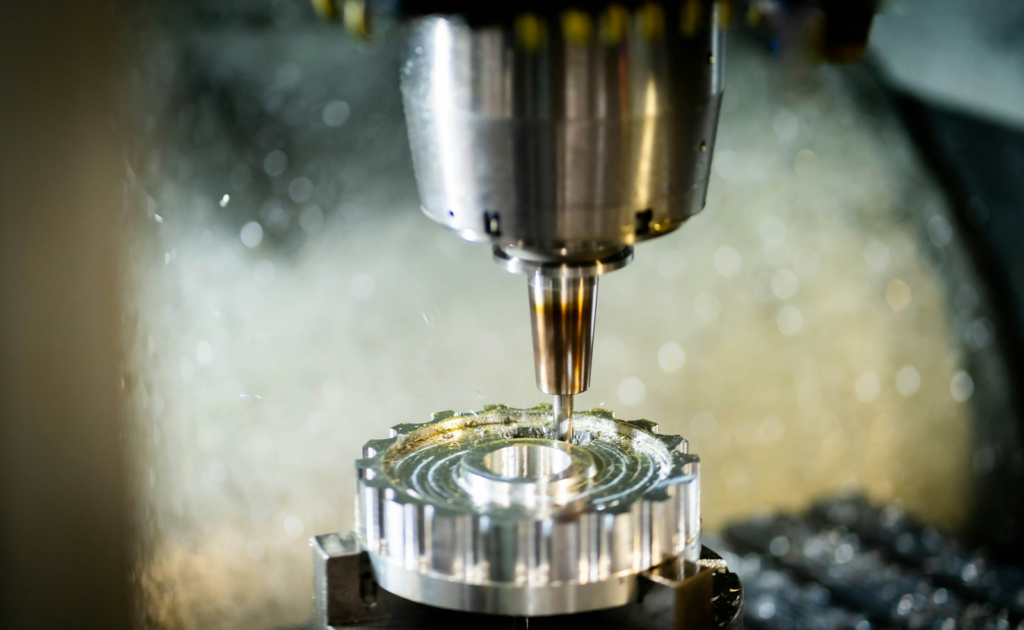
After cutting, most parts need localized features. End milling opens pockets, slots, and mating faces. Cross-drilling adds bolt holes through the profile walls, and tapping puts threads into those holes so the profile can accept fasteners directly. Chamfering and deburring finish the edges so parts handle safely and hardware seats flush.
Aluminum’s softness is an advantage here, but it brings two cautions. First, thin-wall profiles deform under clamp pressure, so fixtures should support large areas at low force rather than clamping hard at a single point. Second, aluminum tends to adhere to cutting tools, which is why sharp, polished flutes and appropriate lubrication matter for both finish and tool life. On hollow profiles, machining near an internal void calls for reduced feed at breakthrough so the exit side does not tear.
Bending and forming
When a design needs a curve or a gradual angle, bending follows extrusion. Roll bending wraps the profile around graduated rollers for large radii, while stretch forming grips the ends and wraps the part over a form for tighter, more repeatable curves. The practical limits come from the alloy and temper: softer tempers bend more easily, and tighter radii increase the risk of wall buckling or distortion on hollow shapes. Bending before full aging, where the schedule allows, reduces springback and cracking risk on demanding geometries.
Aluminum extrusion joining methods
Extruded profiles are most often joined with mechanical fasteners, T-slot hardware, welding, or structural adhesives, and the right choice depends on whether the joint needs to carry load, come apart, or stay invisible.
- T-slot fasteners and corner brackets. Profiles with T-slots accept drop-in nuts and bolts anywhere along the slot, which is what makes modular framing systems adjustable. Corner brackets and gussets stiffen the joints without machining the profile.
- Threaded inserts and tapped ends. Where a profile must bolt to another part, tapping the bore or pressing in a threaded insert creates a durable thread in soft aluminum.
- Welding. MIG and TIG welding produce permanent, load-bearing joints, common in structural and transportation work. Heat from welding can locally reduce temper and distort thin sections, so fixturing and weld sequencing matter.
- Adhesive bonding. Structural adhesives join aluminum to dissimilar materials, spread load over a wider area than a single fastener, and add no heat. Surface preparation is the main quality lever.
- Interference and press fits. For simple assemblies, a sized bore and a press fit eliminate fasteners altogether.
Many products combine several methods: a machine frame might use T-slot brackets for adjustability, tapped holes for components, and adhesive for panels.
What is aluminum extrusion used for?
Aluminum extrusion serves industries that need long, lightweight, corrosion-resistant shapes at production volume, and the machining each application demands varies widely.
- Construction and architecture. Window and curtain wall frames, door frames, and railing systems rely on profiles cut to precise lengths with mitered corners and drainage features machined in.
- Transportation. Truck bodies, rail car structures, and vehicle chassis components use extrusions for weight reduction, with machined interfaces for joints and hardware.
- Solar and renewable energy. Module frames and mounting rails need repeatable cut lengths, punched or drilled mounting holes, and finishes that survive outdoors.
- Electronics and thermal management. Heat sinks and enclosures exploit aluminum’s thermal conductivity; machining adds mounting bosses, connector cutouts, and flat mating surfaces.
- Industrial equipment and automation. Machine frames, workstations, guards, and linear motion structures are built from T-slot profiles assembled with standard hardware.
Across all of these, the pattern is the same: extrusion delivers the efficient cross section, and machining delivers the interfaces that let the profile become a product.
How much does aluminum extrusion machining cost?
Machining cost is driven by a handful of factors that compound: alloy selection, profile complexity, tolerance requirements, order volume, surface finish, and the number of secondary operations. There is no standard public price list, because two parts with the same weight can quote very differently, so it is more useful to understand what moves the number.
| Cost driver | How it affects price |
|---|---|
| Alloy | Common structural alloys machine predictably; harder tempers and special alloys slow cutting and shorten tool life. |
| Profile complexity | Thin walls, multi-void designs, and large cross sections need slower feeds, better fixturing, and more scrap allowance. |
| Tolerance | Standard saw-cut tolerances are inexpensive; every step tighter in tolerance narrows the equipment pool and raises inspection cost. |
| Volume | Setup and fixturing amortize over quantity, so per-part cost drops sharply from prototype to production runs. |
| Surface finish | Anodizing and powder coating are priced separately from machining and add lead time. |
| Secondary operations | Each additional drilling, tapping, or deburring pass adds handling and cycle time. |
Two buyer habits keep quotes predictable. First, specify tolerances you actually need rather than the tightest available, because unnecessary precision is the fastest way to inflate cost. Second, consolidate operations with one supplier where possible; every transfer between shops adds freight, handling damage risk, and lead time.
Extrusion machining versus full CNC machining
Use extrusion when the part has a constant cross section and production volume can amortize the die; use full CNC machining when geometry is complex in three dimensions; combine both when a long profile needs a few precision features. That division is the core decision most buyers face.
| Requirement | Extrusion plus machining | Full CNC machining |
|---|---|---|
| Constant cross section | Excellent, near-zero waste per meter | Possible but machined from solid stock, high waste |
| Complex 3D geometry | Limited to what the die and secondary cuts allow | Excellent |
| Low-volume prototypes | The cost is hard to justify unless standard profiles fit. | Usually practical with no tooling |
| Medium to high volume | Cost-effective per part | Higher material and cycle cost |
| Tight local tolerances | Achieved at machined features | Held across the whole part |
| Design changes | A new die may be required; local machining stays flexible. | Program edits, fast iteration |
Most real products land in the combined column. A long frame rail, for instance, is extruded to shape and then machined only at the mounting faces and holes, which keeps both material usage and cycle time under control. When volumes are small or geometry is fluid, starting with a standard profile and machining it is the lower-risk path; when volumes are large and the shape is stable, a dedicated die plus light machining wins on cost per part.
FAQ
Should you cut aluminum extrusion before or after anodizing?
Cut before finishing whenever the cut edges will be visible or exposed to weather, because anodizing and powder coating protect the freshly cut surface along with the rest of the profile. Cutting after finishing leaves raw aluminum at the edges, which shows as a bright line on dark finishes and corrodes faster outdoors. Cut after finishing only when final length tolerances are so tight that coating buildup would push the part out of spec.
What tolerances can machined aluminum extrusions hold?
As-extruded profiles follow industry-standard tolerance tables that loosen as cross section and length grow. Secondary machining commonly brings individual features to around ±0.1 mm, and precision CNC operations can go tighter on local dimensions. The practical approach is to state the functional requirement—what the feature must mate with—and let the supplier choose the process step that holds it economically.
6061 or 6063: which alloy is better for machined profiles?
6061 offers higher strength and is generally the better choice for structural parts and heavily machined components. 6063 extrudes more easily and takes a cleaner, more uniform anodized finish, which suits architectural profiles where appearance leads. If the part carries load and will see extensive milling and tapping, start with 6061; if surface finish and fine thin-wall detail matter more than strength, 6063 is the usual answer.